29
────────────────────────────────────────────────────
4.5 Starting Measurement
────────────────────────────────────────────────────
Resistance
range
(Ω)
Lead resistance
and contact
resistance
SENSE line break check / Voltage limiter
OFF/ON
(Ω)
OFF/ON
(Ω)
ON/OFF
(Ω)
ON/OFF
(Ω)
30 m
RC1+RL+RC2
RC2
1.4
900 m
400 m
400 m
1.4
300 m
400 m
300 m
300 m
RC1+RL+RC2
RC2
13
7.5
5
5
13
13
5
3.3
3
RC1+RL+RC2
RC2
125
76
55
55
130
34
55
34
30
RC1+RL+RC2
RC2
990
760
260
260
990
333
260
200
300
RC1+RL+RC2
RC2
2.3 k
1.5 k
890
890
2.3 k
640
890
520
3k
RC1+RL+RC2
RC2
8.7 k
5.1 k
3.9 k
3.9 k
8.7 k
1.9 k
3.9 k
330
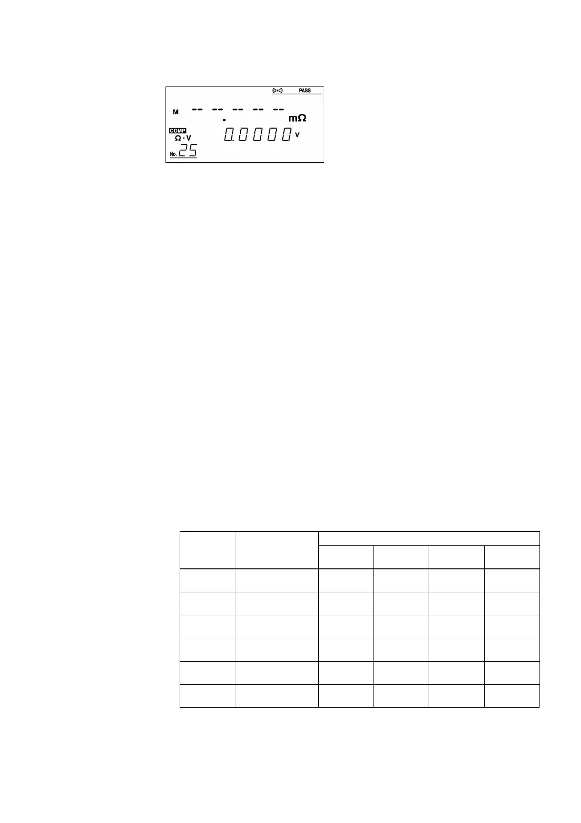
■ In case of abnormal measurements (NG)
When the 3560 monitors the
measurement process and judges the
measurement to be incorrect, it outputs
an abnormal measurements (NG) signal,
displaying "−−−−− " on the fluorescent
character display.
Abnormal measurements include the following events:
・ Broken SOURCE line
・ The SOURCE is not connected to the measured object.
・ The lead resistance of the SOURCE line and the contact resistance and
resistance of the measured object and reactance deviate from the valid
ranges for each parameter. For valid ranges, refer to the following
table.
An abnormal measurement signal is output when any of the following
events occurs. For allowable ranges, see the table below.
・ The SENSE line break check is turned on, and a break has occurred in
the SENSE line.
・ The SENSE line break check is turned on, but the SENSE line is not
connected to the measured object.
・ If the induced voltage is greater than the internal signal processing
level, it is generated between the SOURCE and SENSE lines.
Extending the measurement lead increases induced voltage. If the coil
capacitor has large reactance, the induced voltage may exceed the
internal signal processing level.
・ Immediately following a change in sampling rate
・ Immediately following a change in range
Allowable ranges for SOURCE lead resistance, contact resistance, and
resistance of the measurement object
Figures provided in this table are for reference only; their accuracy is not
guaranteed.
RL: Measurement object
RC1: "Hi" lead resistance + contact resistance
RC2: "Lo" lead resistance + contact resistance
*: RL = F.S.