126
────────────────────────────────────────────────────
10.3 Configuration and Extension of the Measurement Leads
────────────────────────────────────────────────────
■ Reducing induced voltage
Since the 3560 measures a minute resistance with AC power, it is
affected by induced voltage. Induced voltage refers to voltage that allows
the current generated in the 3560 to build an inductive coupling in a lead
and affect signal lines. Since the phase of the induced voltage is shifted
from that of the AC current (reference signal) by 90 degrees, it can be
eliminated with the synchronous detection circuit if the voltage is low.
But for high levels, the induced voltage distorts the signals, causing
incorrect synchronous detection. The 3560 monitors induced voltage
internally and generates an abnormal measurement signal if the level
rises above a certain level. Reducing the length of the lead will lower
induced voltage. Reducing the length of the branched section is
particularly effective.
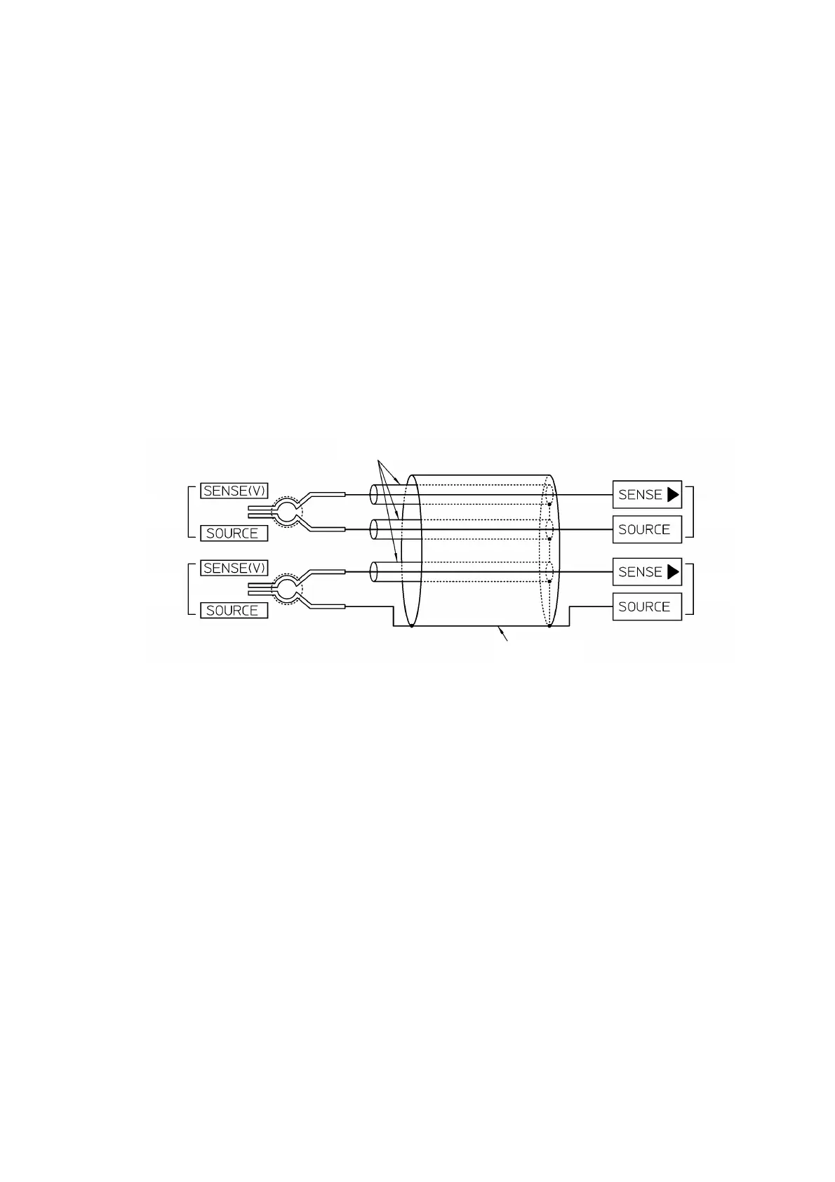
■ Measurement lead structure
The figure below illustrates the structure of the measurement lead.