Assembly and Commissioning Instructions Servo amplifier D1-N 15.10.2015
Overview of electrical connections
All of the D1-N's connections are labelled and designed to be pluggable, ensuring
simple installation and rapid device replacement. All mating connectors are sup-
plied. Figure 5.1 provides an overview of all connections on the D1-N drive amplifi-
er.
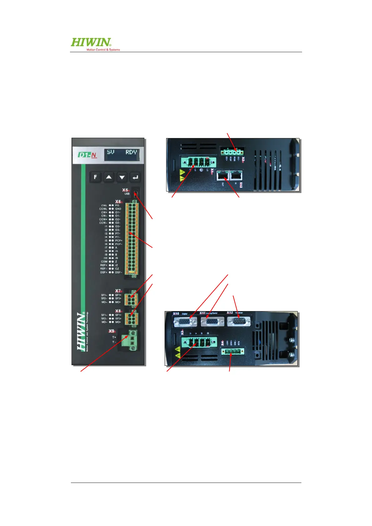
Figure 5.1: Overview of electrical connections
X1 - mains connection
X13 – EtherCAT (option)
– brake resistor connection
X5 – parameterisation interface
X6 – inputs / outputs connection
X7 – input STO
– output STO
– motor temperature sensor
X4 – control voltage
and brake connection
– motor connection
X10 – digital encoder connection
X11- analogue encoder connection
X12 – revolver encoder connection

 Loading...