Assembly and Commissioning Instructions Servo amplifier D1-N 15.10.2015
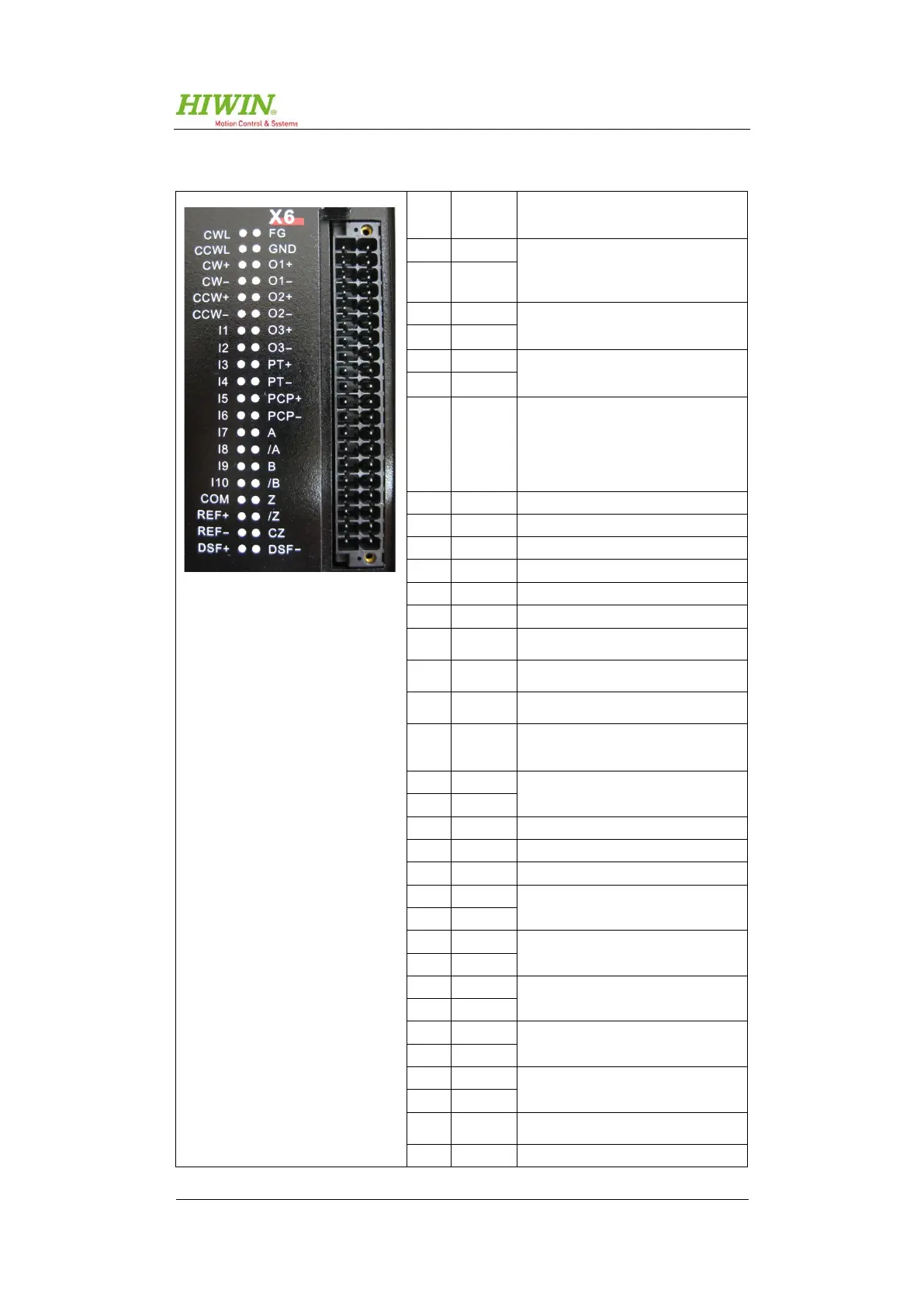
X6 – Input and output connection
1 CWL
(12 VDC and 24 VDC) for step/
direction input
2 CCWL
3 CW+
Channel 1 for step/direction input
(step, CW, track A)
(see chapter 5.7.1)
4 CW-
5 CCW+
Channel 2 for step/direction input
(direction, CCW, track B)
6 CCW-
7 I1
Depending on the device type:
D1-N-xx-Sx-x-x-xx: Motor enable
D1-N-xx-Ex-x-x-xx: programmable as
motor enable or not used
D1-N-xx-Fx-x-x-xx: programmable as
8 I2 Digital input 2, programmable
9 I3 Digital input 3, programmable
10 I4 Digital input 4, programmable
11 I5 Digital input 5, programmable
12 I6 Digital input 6, programmable
13 I7 Digital input 7, programmable
14 I8
Digital input 8, programmable
(no function with EnDat 2.2)
15 I9
Digital input 9, programmable
(no function with EnDat 2.2)
16 I10
Digital input 10, programmable
(no function with EnDat 2.2)
17 COM
Selection of switching characteristics
for digital inputs I1 to I10.
18 Ref+
Analogue input for speed and torque
nominal values.
19 Ref-
20 DSF+ Reset function output for STO
21 FG Connection for I/O cable shielding
22 GND GND
23 O1+
Digital output 1, programmable
24 O1-
25 O2+
Digital output 2, programmable
26 O2-
27 O3+
Digital output 3, programmable
28 O3-
29 PT+
Digital output of cam group
30 PT-
31 PCAP+
Capture input
32 PCAP-
33 A
Encoder output track A, differential
(see chapter 5.7.3)
34 /A Encoder output track /A, differential

 Loading...