Assembly and Commissioning Instructions Servo amplifier D1-N 15.10.2015
X2 – brake resistor connection
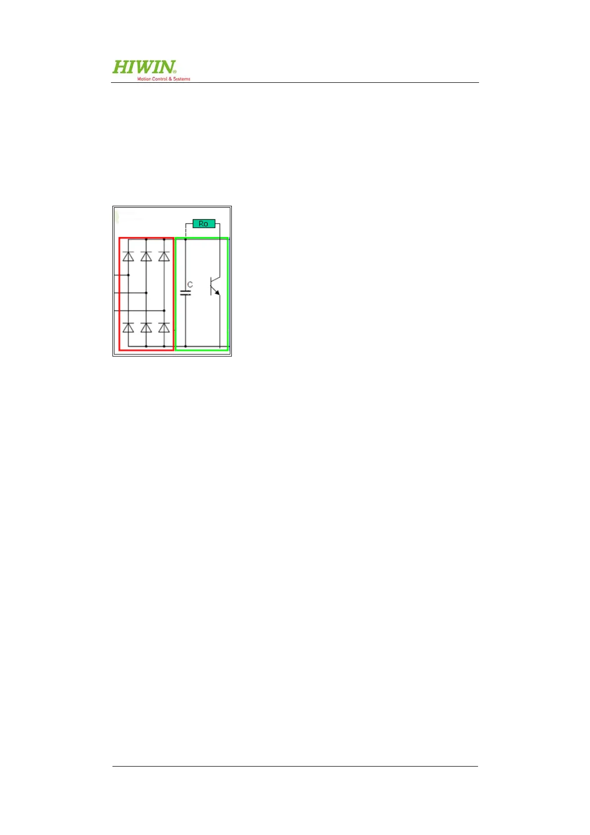
When an electric drive is braked, the kinetic energy is converted into electric ener-
gy and fed back to the drive amplifier's intermediate circuit. The energy fed back is
absorbed by the internal capacitors provided they have sufficient capacity. If not,
the excess energy must be dissipated via a brake resistor. Figure 5.5 contains a
diagram of the intermediate circuit in the D1-N.
Figure 5.5: Intermediate circuit
The devices D1-N-09, D1-N-18, and D1-N-36 are fitted with an internal brake re-
sistor of 50 Ω/150 W. The D1-N-90 does not have an internal brake resistance.
Should high levels of dynamism mean that the D1-N's internal brake resistor is
insufficient, an additional brake resistor can be connected to the X2 connector (also
refer to section 5.3.1 on page 33).
This additional brake resistor can be connected to the X2 connector as shown in
Figure 5.6 on page 33.
 Loading...
