Assembly and Commissioning Instructions Servo amplifier D1-N 15.10.2015
X4 – control voltage and motor brake connection
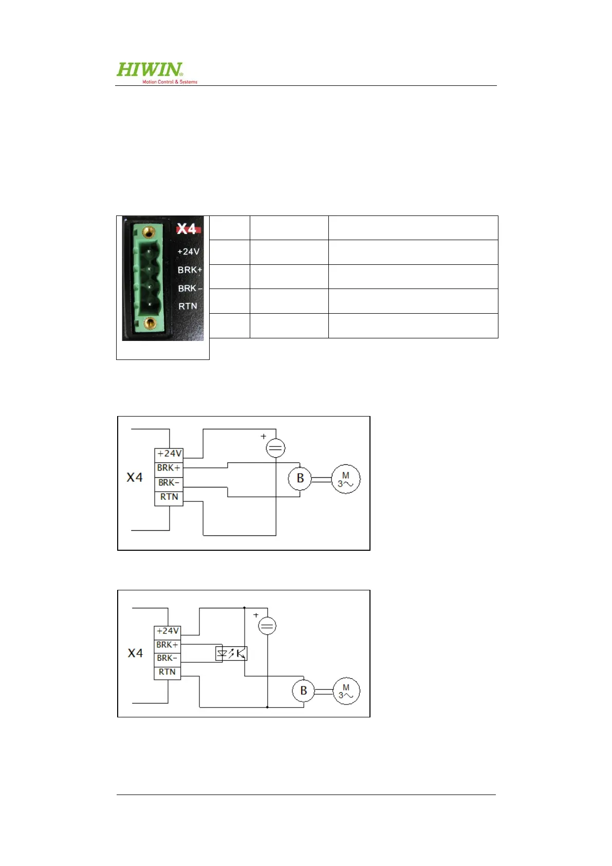
The D1-N allows motors with an electric brake to be controlled. The brake output
supplies a voltage of 24 VDC and a current of up to 1 A. For brakes requiring other
voltages or higher currents, we would recommend a relay or optocoupler circuit
(see Figure 5.8, Figure 5.9 and Figure 5.10).
You will find more information about the brake configuration in section 8.6.
+24 V +24 VDC (control voltage)
BRK+ Brake connection +
BRK- Brake connection -
RTN GND (24 VDC)
Table 5.6: X4 – control voltage and motor brake connection
Figure 5.8: Direct brake control
Figure 5.9: Brake control via optocoupler

 Loading...