114 / 183
Assembly and Commissioning Instructions Servo amplifier D1-N
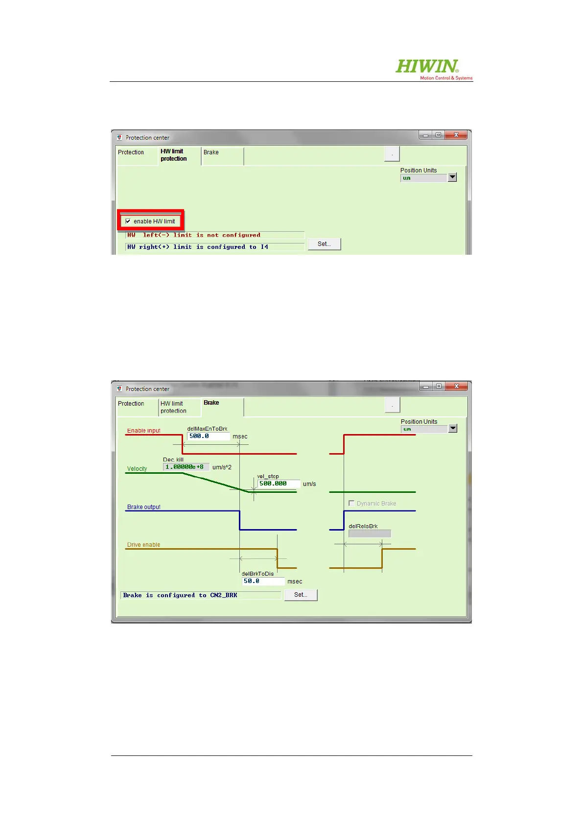
If limit switches are used, switch monitoring can be activated in this tab.
Figure 8.72: “Protection center” – HW limit protection
The relevant inputs for limit switches can be configured in the
See
capture
8.7.
The "Brake" tab clearly shows all the parameters needed to configure the brake
behaviour.
Figure 8.73: “Protection center” – Brake
 Loading...
