INTRODUCTION
Part. No. 2400M2501_6 Touchpoint Pro
17 Technical Handbook
3.3.10 TPPR Backplane
The TPPR Backplane is the power and information highway to which all of the TPPR modules are attached. There can be
several backplanes in larger units, and they are installed within the DIN rail to which the modules are clipped.
The Backplane is available in four lengths (270 mm, 350 mm, 430 mm, 480 mm) to suit 5, 7, 9 or 10 I/O modules
respectively, but the choice may be restricted by the size of the selected power supply option and the need to maintain
adequate cooling space between modules.
Note: The DIN rail is 430 mm for a standard enclosure or 487 mm for the wide enclosure (10 x I/O) option.
Figure 21. TPPR Backplane
The Power Supply Unit (PSU) plugs into the green socket on the left hand side of the Backplane PCB, and it supplies power
to the modules via the white connectors. The Ring Coupling Module (RCM) normally sits next to the Power Connector and
handles all of the bi-directional communication between the CCB and the modules, again via the white connectors.
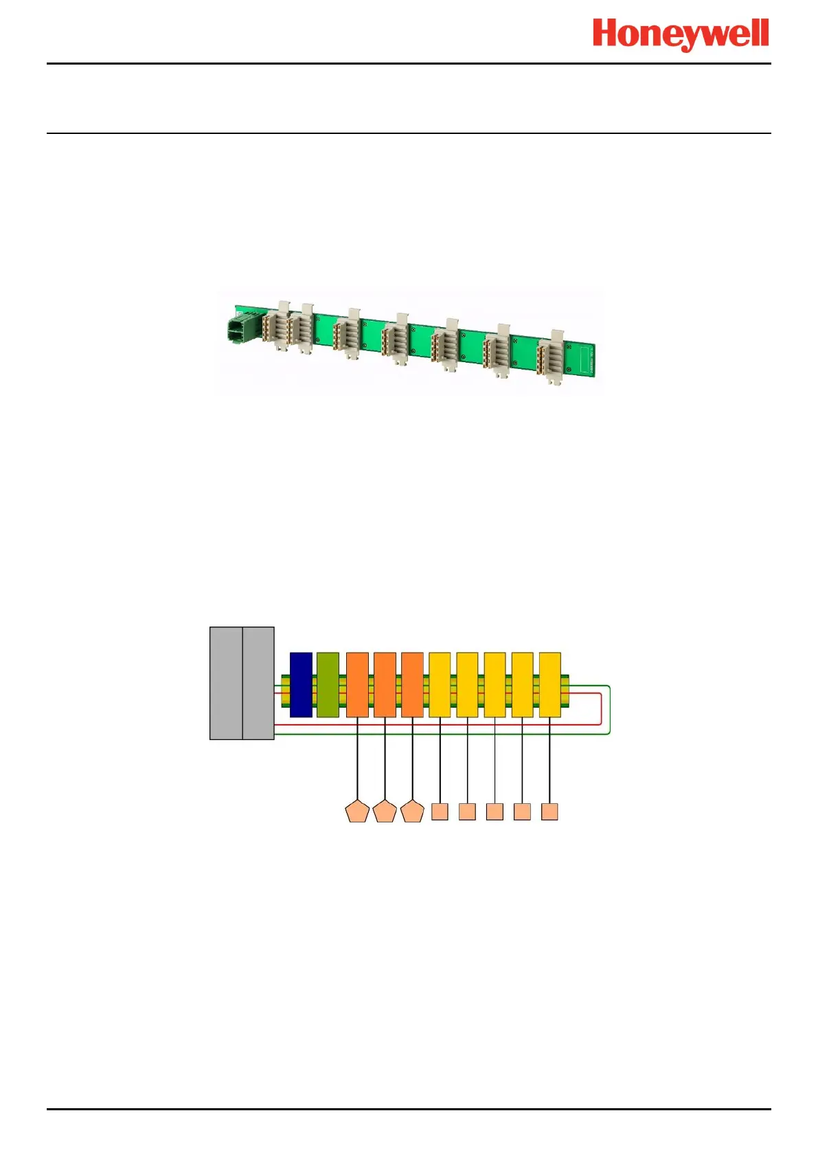
3.3.11 Ring Network
The Ring Coupling Module (RCM) and Input / Output (I/O) modules connect to a dual ring circuit so that they can
communicate with the CCB through each other and through the RCM.
This enables fail-safe redundancy because, if one addressable module fails and interrupts the primary circuit, the
addressable modules on either side of it can still communicate with the CCB via the backup ring circuit (see diagram below),
and the CCB can identify which module has failed by knowing which addressable modules are still active.
Figure 22. TPPR Controller Typical Schematic
Field Device
Output Modules
RCM Redundancy
Module (option)
TPPR- Activated Field Devices
Communication Board
(COB)
Control Centre Board
(CCB)
 Loading...


