MODBUS INSTALLATION
Part. No. 2400M2501_6 Touchpoint Pro
35 Technical Handbook
5.2.4 Ethernet Cables
Ethernet cable must be CAT5e or CAT6 Ethernet cable terminated to TIA/EIA-568B standard. The cable should have
shielded RJ45 plugs with the shield of the cable bonded to the metal body (shield) of the connector plug. The cable length
should not exceed 100 m. The Ethernet cable should be fitted through a gland to preserve the IP rating where appropriate.
5.2.5 TPPR Battery Box Cables
Connect the TPPR Battery enclosure to protective earth using a minimum wire size of 6 mm
2
(10 AWG) and the M8
Protective Earth (ground) stud.
The cable between the TPPR System UPS and the TPPR Battery Box must be 4 mm² / AWG 7; UL/CSA approved wiring
material, tri-rated (105 °C). The maximum cable length between the Battery Box and the UPS is 5 m. Bootlace ferrules must
be used on all stranded cable end terminations except for the battery-end spade terminals (supplied).
5.2.6 24 VDC Power Cables
24 VDC power cables should be rated appropriate to the current load.
The Modules will accept a maximum wire size of 1.5 mm² / AWG 15 and the DIN rail connector will accept a maximum wire
size of 6 mm² / AWG 3.
5.2.7 Ring Network Cables
Ring network wiring should use good quality signal cabling suitable for RS485 signals.
The external ring network cabling should be shielded and grounded twisted pair cables. The terminals will accept a
maximum wire size of 1.5 mm² / AWG 15.
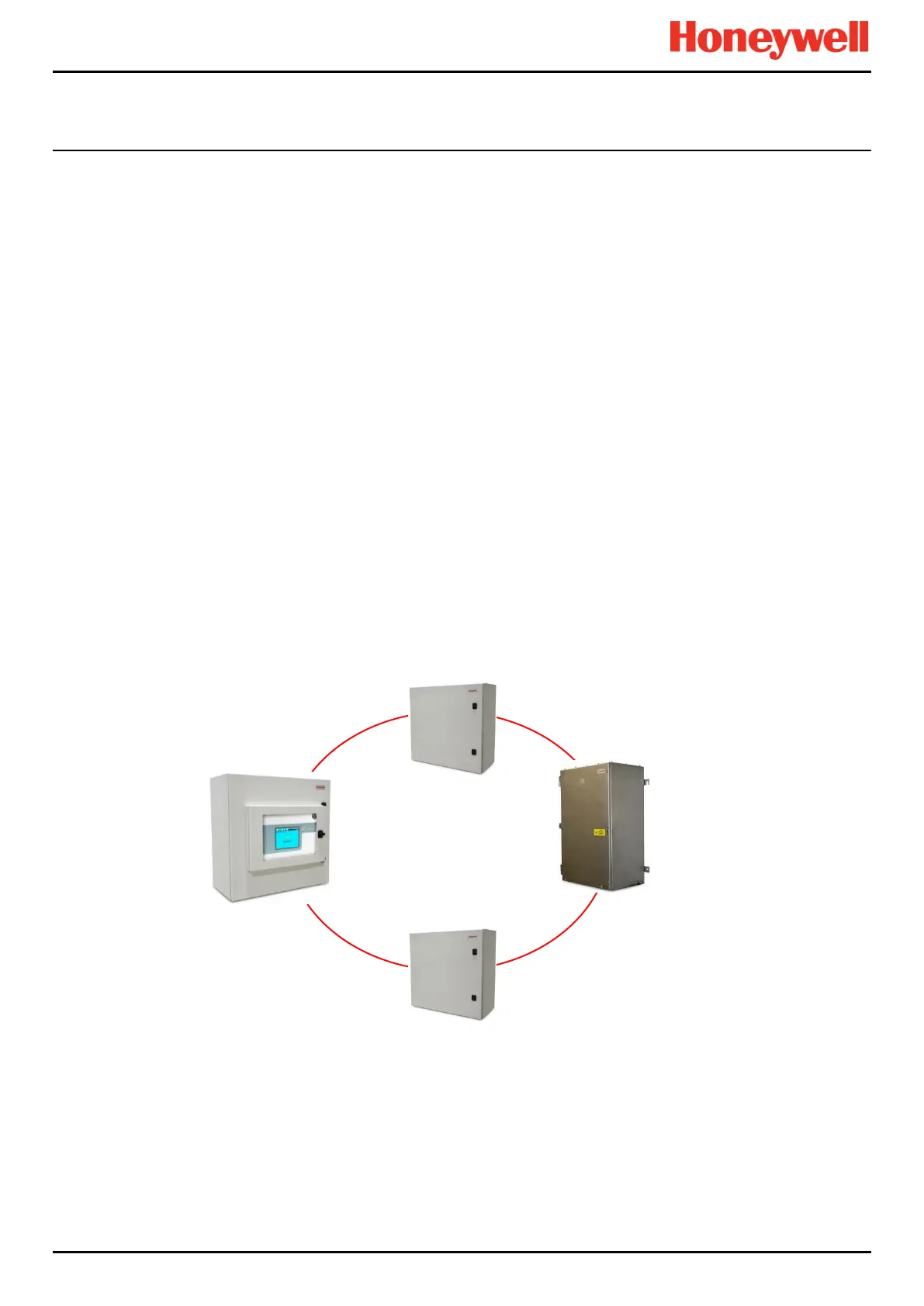
5.2.8 Ring Network Cable Restrictions
The TPPR total ring network cabling must not exceed 3 km (1.86 miles). The distance between individual TPPR units (i.e.
between a Controller and a Remote Unit) must not exceed 1 km (0.62 miles).
Figure 41. Ring Network Maximum Distances

 Loading...


