MODBUS INSTALLATION
Part. No. 2400M2501_6 Touchpoint Pro
36 Technical Handbook
5.2.9 Earthing (Grounding)
5.2.10 Location of the Primary TPPR Protective Earth (Ground) Connection Stud
The primary TPPR protective earth (protective ground) stud is marked with a green earth (ground) label, and can be found:
Standard enclosures – lower left corner
Rack mount units – reverse side, lower left corner
Instrument and common earth (ground) points are marked with a black and white earth label.
5.2.11 Cable Shielding (Screening)
Field device cable shielding shall be connected to instrument earth (ground) at the respective TPPR controller or remote unit
only, and the opposite end shall be isolated from contact with any metal body or cable.
Factory supplied enclosures contain a pre-fitted bus bar for earthing the field cables and it is recommended that OEMs fit
them in their custom TPPR enclosures / racks.
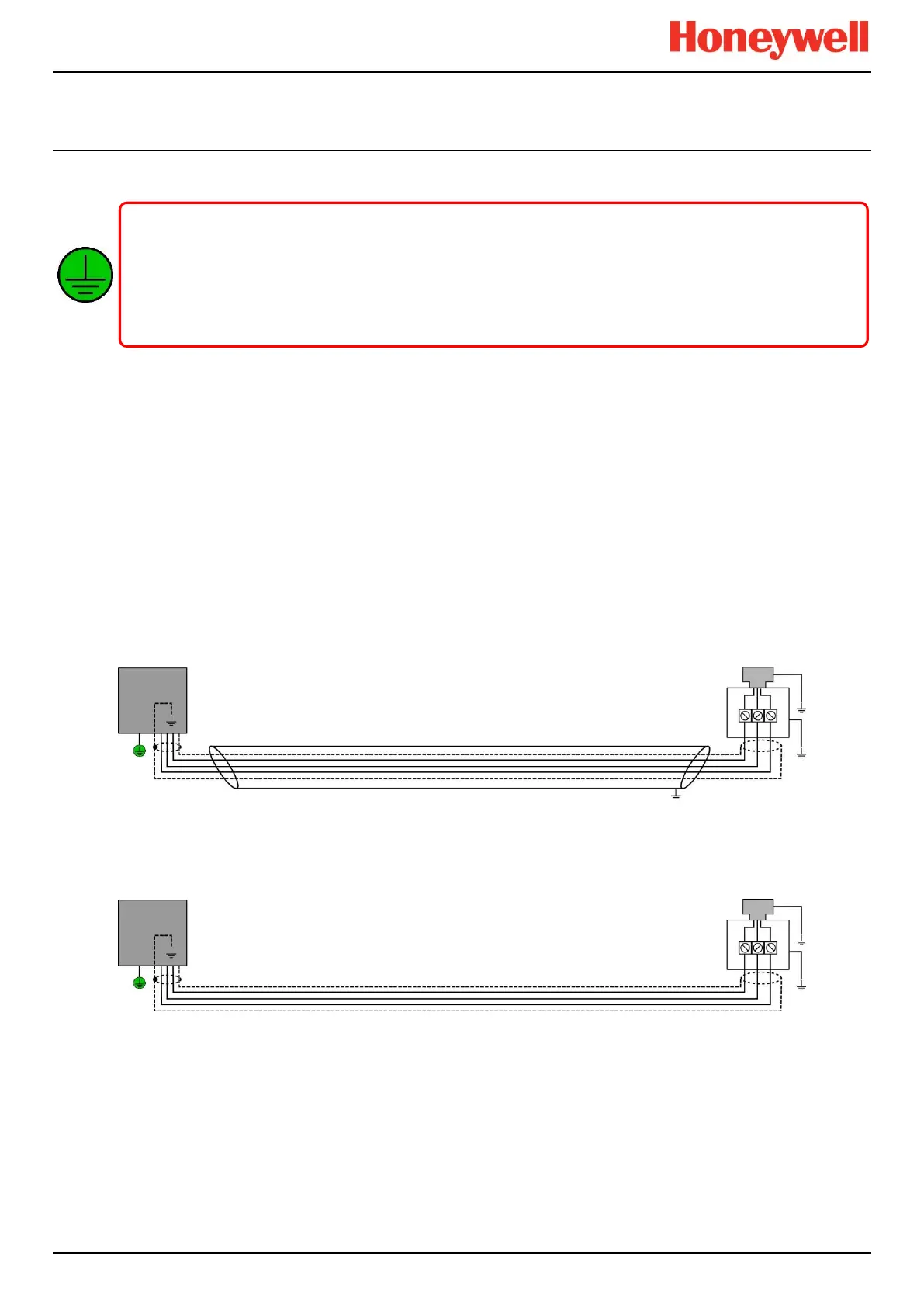
The diagrams below show some examples of acceptable TPPR earthing and shielding practice.
Figure 42. Shielding with Metal Armour, Metal Junction Box and Metal Sensor Body
Figure 43. Shielding with no Armour, Metal Junction Box and Metal Sensor Body
All TPPR equipment, sensors and cable shielding shall be earthed (grounded) using only the dedicated TPPR earth
terminals or common earth rail. Do not disturb or remove factory-fitted earth connections.
All cable armour and/or metal conduits shall be separately earthed and isolated from the TPPR, its equipment and
its attached cables.
Avoid creating earth (ground) loops.

 Loading...


