EasyManua.ls Logo

Honeywell touchpoint Pro - Navigation - Inputs and Outputs Screens

Honeywell touchpoint Pro
200 pages
To Next Page IconTo Next Page
To Previous Page IconTo Previous Page
Loading...
CONFIGURATION
Part. No. 2400M2501_6 Touchpoint Pro
87 Technical Handbook
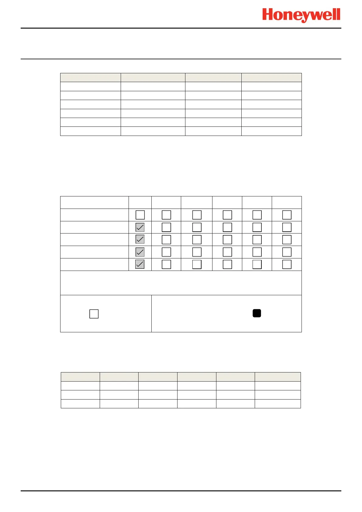
For example:
Condition 1
Condition 2
Condition 3
Output State
Channel 1 A1
Channel 2 A1
Activated
Channel 1 A1
Channel 3 A1
Activated
Channel 1 A1
Channel 2 A1
Channel 3 A1
Activated
Channel 1 A1
Channel 3 Fault
Activated
Channel 2 A1
Channel 3 A1 and Fault
Activated
Channel 3 A1
Channel 3 Fault
Not Activated
In the example, if the vote count is set to 1, any one or more input channels with an active event will cause the output to
activate. Similarly, if the vote count is set to 3, each input must have at least one active event to cause the output to activate.
9.6.5 Vote Compensation (Vote Reduction)
If a voting input is inhibited or has a fault, it can prevent a voted output from activating as expected. Vote compensation may
be used to take account of failing or inhibited inputs.
ID/Location
AL1
AL2
AL3
FLT
INH
WRN
Select All
i01 Channel 1
i02 Channel 2
i03 Channel 3
i04 Channel 4
At least One Alarm
Enabled
Vote Count
Channels Selected:
4
In the example above, 3 inputs are required to be in an alarm state to activate the output. If, for instance, two inputs are in a
fault or inhibit state, only two inputs are able to vote. The output cannot activate, even if both remaining inputs alarm:
Channel 1
Channel 2
Channel 3
Channel 4
Count
Output State
AL1
AL1
AL1
Don’t care
3
Activated
Fault
AL1
AL1
AL1
3
Activated
Fault
AL1
Inhibit
AL1
2
Not Activated
3

Table of Contents

Other manuals for Honeywell touchpoint Pro

Related product manuals