EasyManuals Logo

Honeywell touchpoint Pro Technical Handbook

Honeywell touchpoint Pro
200 pages
To Next Page IconTo Next Page
To Previous Page IconTo Previous Page
Page #95 background imageLoading...
Page #95 background image
CONFIGURATION
Part. No. 2400M2501_6 Touchpoint Pro
88 Technical Handbook
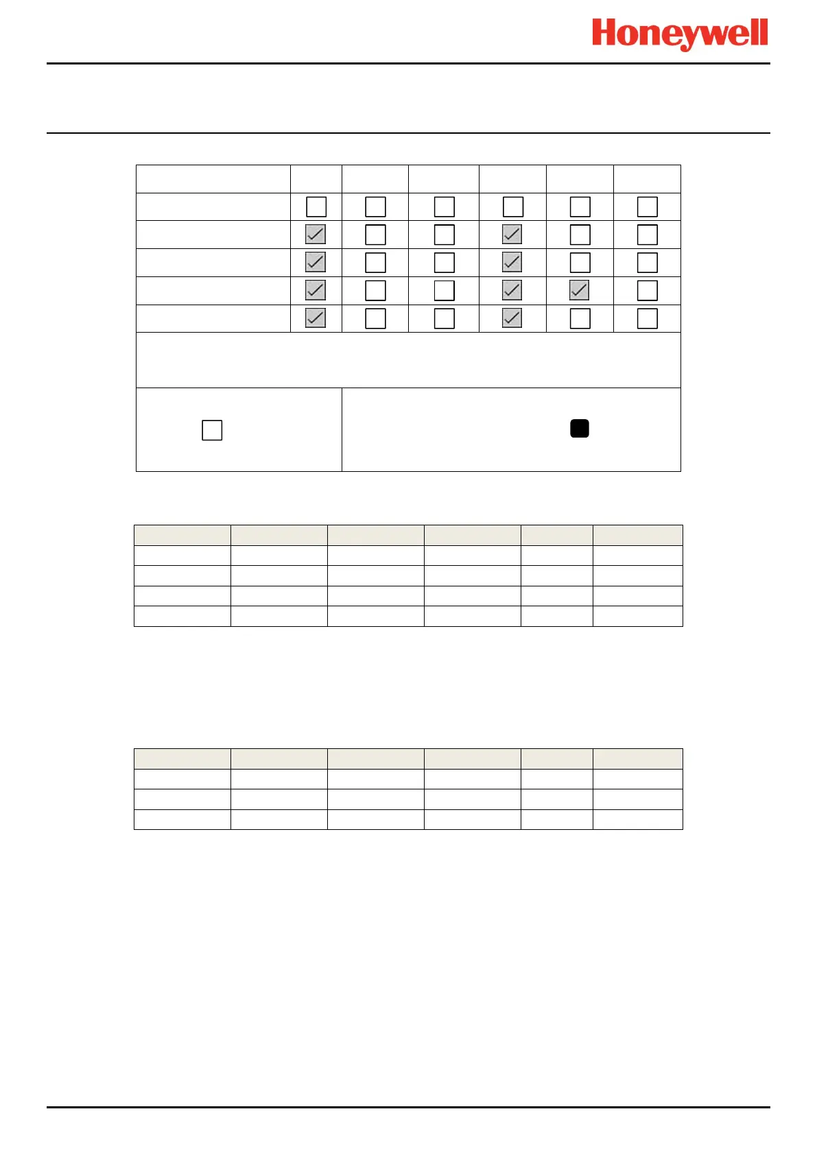
TPPR allows the fault and inhibit conditions to be included in the vote, simply by checking the options for those inputs.
ID/Location
AL1
AL2
AL3
FLT
INH
WRN
Select All
i01 Channel 1
i02 Channel 2
i03 Channel 3
i04 Channel 4
At least One Alarm
Enabled
Vote Count
Channels Selected:
4
Then the output may be activated as follows:
Channel 1
Channel 2
Channel 3
Channel 4
Count
Output State
AL1
AL1
AL1
Don’t care
3
Activated
Fault
AL1
AL1
AL1
4
Activated
Fault
AL1
Inhibit
AL1
4
Activated
Inhibit
AL1
AL1
Normal
2
Not Activated
9.6.6 Requiring At Least One Alarm
When faults and inhibit conditions are included in the cause and effect logic, it may be possible to activate an output with
Fault and Inhibits only. Using the above cause and effect example:
Channel 1
Channel 2
Channel 3
Channel 4
Count
Output State
Fault
Fault
Fault
Don’t care
3
Activated
Fault
Don’t care
Inhibit
Fault
3
Activated
Normal
Fault
Inhibit
Fault
3
Activated
3

Table of Contents

Other manuals for Honeywell touchpoint Pro

Questions and Answers:

Question and Answer IconNeed help?

Do you have a question about the Honeywell touchpoint Pro and is the answer not in the manual?

Honeywell touchpoint Pro Specifications

General IconGeneral
BrandHoneywell
Modeltouchpoint Pro
CategoryControl Systems
LanguageEnglish

Related product manuals