175
[DeviceA] mirroring-group 1 reflector-port gigabitethernet 1/0/5
This operation may delete all settings made on the interface. Continue? [Y/N]:y
# Create VLAN 10, and assign ports GigabitEthernet 1/0/11 through GigabitEthernet 1/0/13 to VLAN
10.
[DeviceA] vlan 10
[DeviceA-vlan10] port gigabitethernet 1/0/11 to gigabitethernet 1/0/13
[DeviceA-vlan10] quit
# Configure VLAN 10 as the remote probe VLAN of the remote source group.
[DeviceA] mirroring-group 1 remote-probe vlan 10
Layer 3 remote port mirroring configuration example
Network requirements
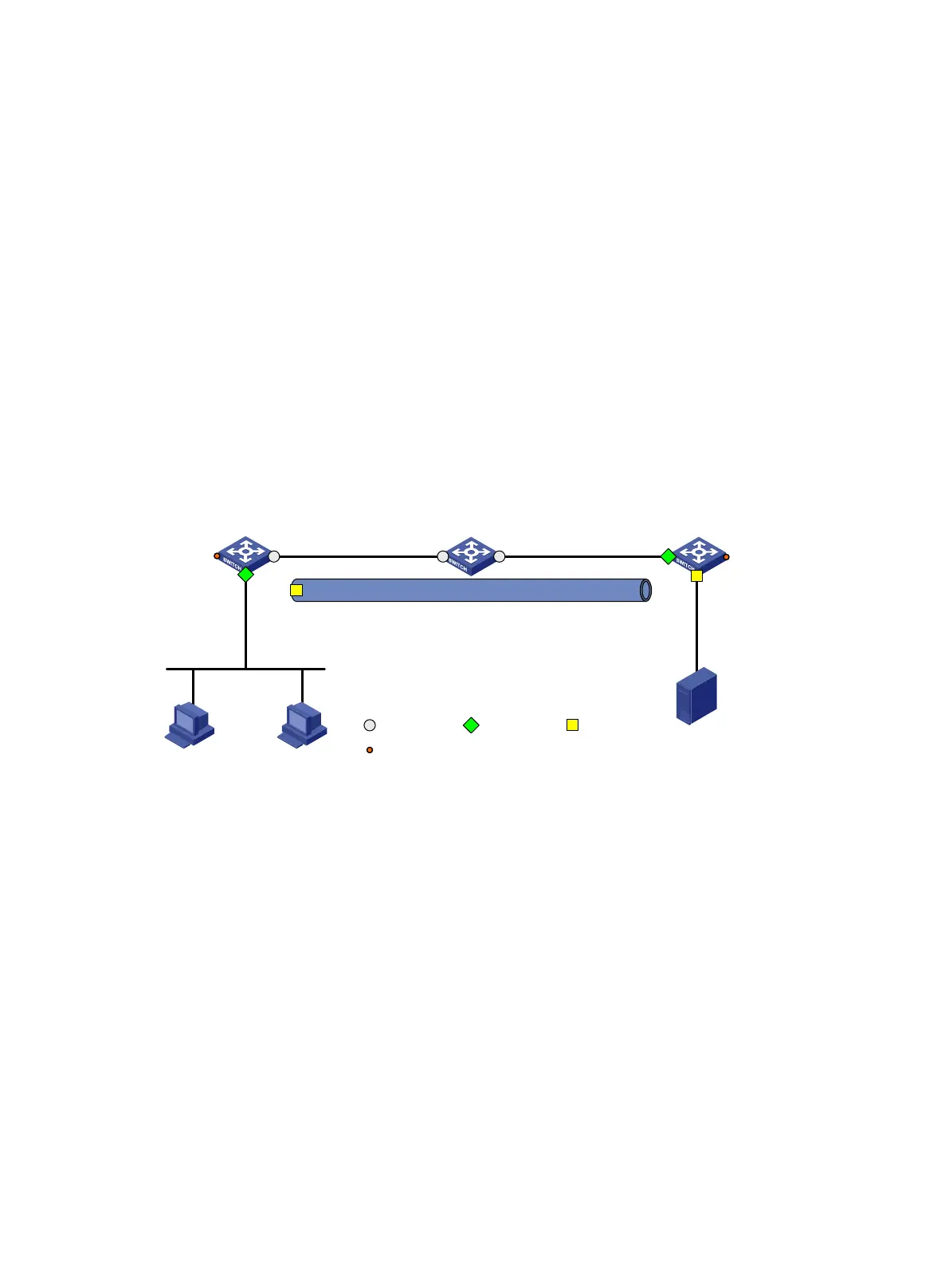
As shown in Figure 66, configure Layer 3 remote port mirroring so the server can monitor the
bidirectional traffic of the Marketing department.
Figure 66 Network diagram
Configuration procedure
1. Configure IP addresses for the tunnel interfaces and related ports on the devices. (Details not
shown.)
2. Configure Device A (the source device):
# Create service loopback group 1, and specify the tunnel service for the group.
<DeviceA> system-view
[DeviceA] service-loopback group 1 type tunnel
# Assign GigabitEthernet 1/0/3 to service loopback group 1.
[DeviceA] interface gigabitethernet 1/0/3
[DeviceA-GigabitEthernet1/0/3] port service-loopback group 1
All configurations on the interface will be lost. Continue?[Y/N]:y
[DeviceA-GigabitEthernet1/0/3] quit
# Create tunnel interface Tunnel 0 that operates in GRE mode, and configure an IP address
and subnet mask for the interface.
[DeviceA] interface tunnel 0 mode gre
[DeviceA-Tunnel0] ip address 50.1.1.1 24
# Configure source and destination IP addresses for Tunnel 0.
GE1/0/2
40.1.1.1/24
Source
device
Device A
GE1/0/1
10.1.1.1/24
Server
Marketing
dept.
Destination
device
Device C
Tunnel0
50.1.1.1/24
Tunnel0
50.1.1.2/24
GE1/0/2
20.1.1.1/24
GE1/0/2
30.1.1.1/24
GE1/0/1
20.1.1.2/24
GE1/0/1
30.1.1.2/24
GRE tunnel
Intermediate
device
Device B
Source port Monitor port
Common port
GE1/0/3
GE1/0/3
Service loopback interface

 Loading...


