172
Layer 2 remote port mirroring configuration example
Network requirements
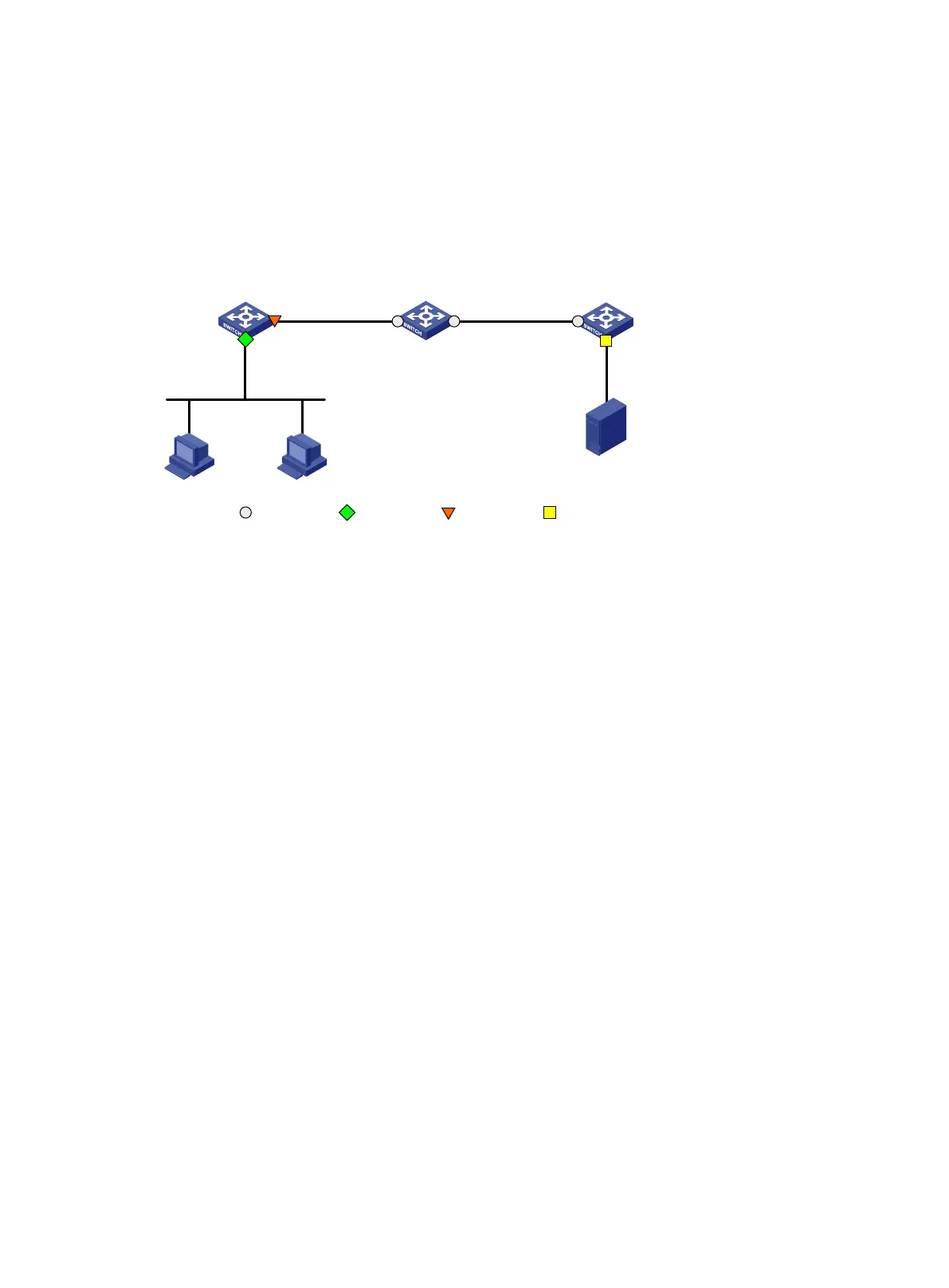
As shown in Figure 64, configure Layer 2 remote port mirroring so the server can monitor the
bidirectional traffic of the Marketing department.
Figure 64 Network diagram
Configuration procedure
1. Configure Device C (the destination device):
# Configure GigabitEthernet 1/0/1 as a trunk port to permit the packets from VLAN 2 to pass
through.
<DeviceC> system-view
[DeviceC] interface gigabitethernet 1/0/1
[DeviceC-GigabitEthernet1/0/1] port link-type trunk
[DeviceC-GigabitEthernet1/0/1] port trunk permit vlan 2
[DeviceC-GigabitEthernet1/0/1] quit
# Create a remote destination group.
[DeviceC] mirroring-group 2 remote-destination
# Create VLAN 2.
[DeviceC] vlan 2
# Disable MAC address learning for VLAN 2.
[DeviceC-vlan2] undo mac-address mac-learning enable
[DeviceC-vlan2] quit
# Configure VLAN 2 as the remote probe VLAN and GigabitEthernet 1/0/2 as the monitor port of
the mirroring group.
[DeviceC] mirroring-group 2 remote-probe vlan 2
[DeviceC] interface gigabitethernet 1/0/2
[DeviceC-GigabitEthernet1/0/2] mirroring-group 2 monitor-port
# Disable the spanning tree feature on GigabitEthernet 1/0/2.
[DeviceC-GigabitEthernet1/0/2] undo stp enable
# Assign GigabitEthernet 1/0/2 to VLAN 2 as an access port.
[DeviceC-GigabitEthernet1/0/2] port access vlan 2
[DeviceC-GigabitEthernet1/0/2] quit
2. Configure Device B (the intermediate device):
Source
device
Device A
GE
1/
0
/1
GE
1/
0
/2
Server
Marketing
Dept
.
Intermediate
device
Device
B
Destination
device
Device C
GE1
/0
/
1 GE
1/
0
/2
GE1
/
0/
1
GE1
/0
/
2
Source port Monitor port
Egress port
Common port
VLAN
2
VLAN 2

 Loading...


