151
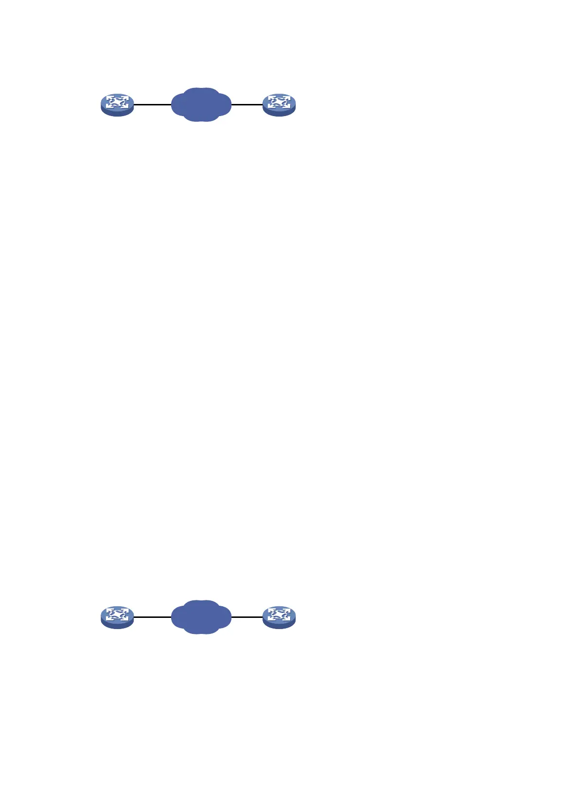
Figure 53 Network diagram
Configuration procedure
1. Assign IP addresses to interfaces, as shown in Figure 53. (Details not shown.)
2. Configure static routes or a routing protocol to make sure the devices can reach each other.
(Details not shown.)
3. Configure Device B:
# Enable the NQA server.
<DeviceB> system-view
[DeviceB] nqa server enable
# Configure a listening service to listen to the IP address 10.2.2.2 and TCP port 9000.
[DeviceB] nqa server tcp-connect 10.2.2.2 9000
4. Configure Device A:
# Create TCP template tcp.
<DeviceA> system-view
[DeviceA] nqa template tcp tcp
# Specify 10.2.2.2 as the destination IP address.
[DeviceA-nqatplt-tcp-tcp] destination ip 10.2.2.2
# Set the destination port number to 9000.
[DeviceA-nqatplt-tcp-tcp] destination port 9000
# Configure the NQA client to notify the feature of the successful operation event if the number
of consecutive successful probes reaches 2.
[DeviceA-nqatplt-tcp-tcp] reaction trigger probe-pass 2
# Configure the NQA client to notify the feature of the operation failure if the number of
consecutive failed probes reaches 2.
[DeviceA-nqatplt-tcp-tcp] reaction trigger probe-fail 2
TCP half open template configuration example
Network requirements
As shown in Figure 54, configure a TCP half open template for a feature to test whether Device B can
provide the TCP service for Device A.
Figure 54 Network diagram
Configuration procedure
1. Assign IP addresses to interfaces, as shown in Figure 54. (Details not shown.)
2. Configure static routes or a routing protocol to make sure the devices can reach each other.
(Details not shown.)
NQA client
Device A
IP network
Device B
10.1.1.1/16
10.
2.
2
.2
/16
NQA server
NQA client
Device A
IP network
Device B
10.1.1
.1/16 10.
2.2.2/16
NQA server

 Loading...


