31
Stability: 0.000 pps
Clock precision: 2^-10
Root delay: 0.01855 ms
Root dispersion: 9.23483 ms
Reference time: d0c6047c.97199f9f Wed, Dec 29 2010 19:03:24.590
# Verify that an IPv6 NTP association has been established between Device B and Device A.
[DeviceB] display ntp-service ipv6 sessions
Notes: 1 source(master), 2 source(peer), 3 selected, 4 candidate, 5 configured.
Source: [1234]3000::35
Reference: 127.127.1.0 Clock stratum: 2
Reachabilities: 15 Poll interval: 64
Last receive time: 19 Offset: 0.0
Roundtrip delay: 0.0 Dispersion: 0.0
Total sessions: 1
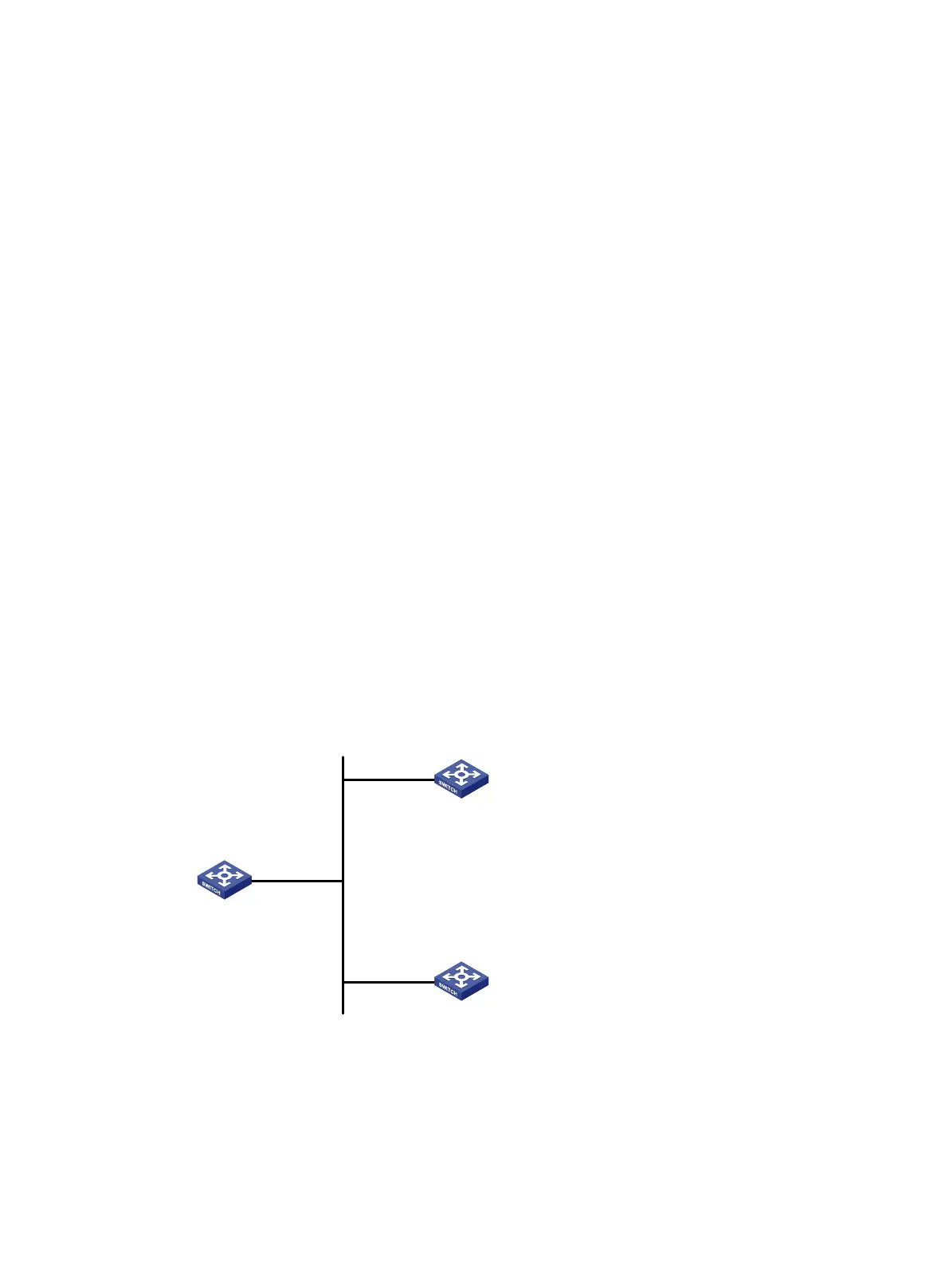
NTP broadcast mode configuration example
Network requirements
As shown in Figure 13, Switch C functions as the NTP server for multiple devices on a network
segment and synchronizes the time among multiple devices.
• Configure Switch C's local clock as a reference source, with the stratum level 2.
• Configure Switch C to operate in broadcast server mode and send out broadcast messages
from VLAN-interface 2.
• Configure Switch A and Switch B to operate in broadcast client mode, and listen to broadcast
messages through VLAN-interface 2.
Figure 13 Network diagram
Configuration procedure
1. Set the IP address for each interface, and make sure Switch A, Switch B, and Switch C can
reach each other, as shown in Figure 13. (Details not shown.)
2. Configure Switch C:
# Enable the NTP service.
Vlan-int2
3.0.1.31/24
Vlan-int2
3.0.1.32/24
Vlan-int2
3.0.1.30/24
Switch A
NTP broadcast client
Switch C
NTP broadcast server
Switch B
NTP broadcast client

 Loading...


