159
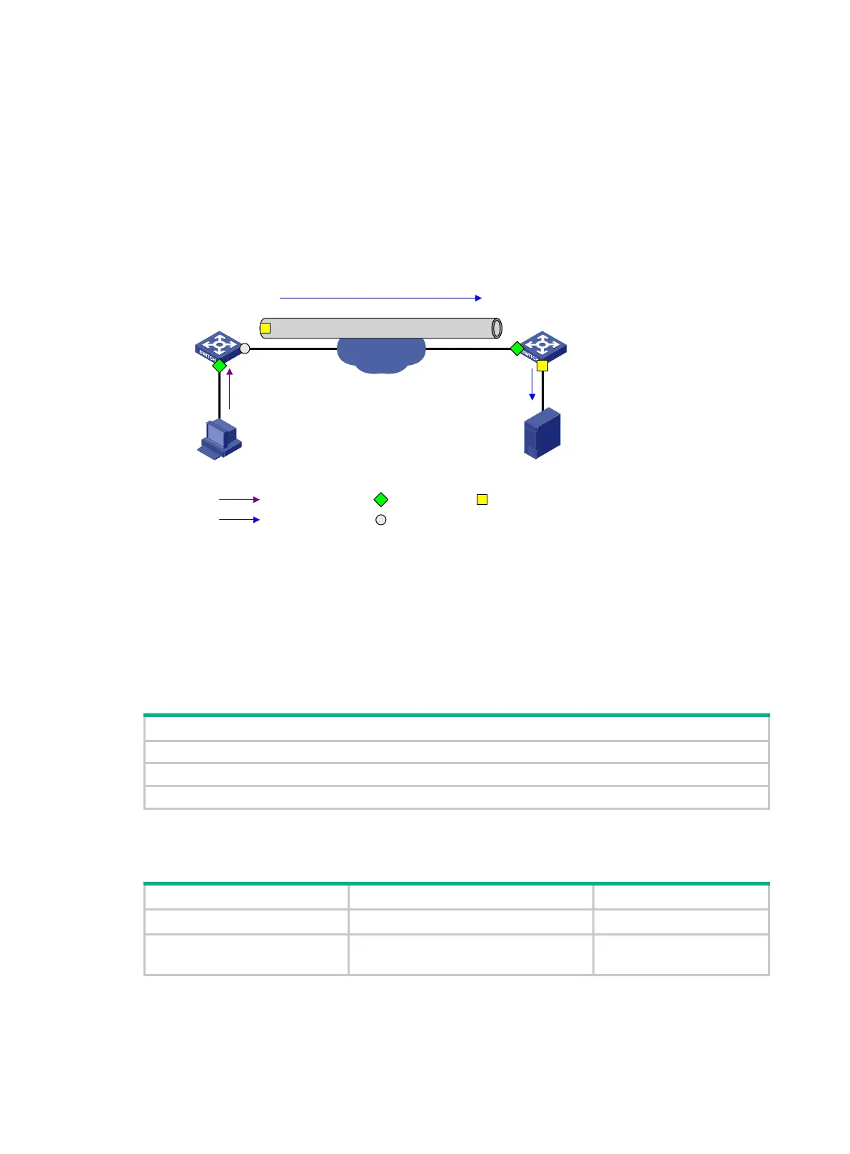
c. The destination device receives the mirrored packet from the physical interface of the tunnel
interface.
The tunnel interface acts as the source port in the local mirroring group created on the
destination device.
d. The physical interface of the tunnel interface sends one copy of the packet to the monitor
port GigabitEthernet 1/0/2.
e. GigabitEthernet 1/0/2 forwards the packet to the data monitoring device.
For more information about GRE tunnels and tunnel interfaces, see Layer 3—IP Services
Configuration Guide.
Figure 62 Layer 3 remote port mirroring implementation
Configuring local port mirroring
A local mirroring group takes effect only when you configure the source ports and the monitor port for
the local mirroring group.
Local port mirroring configuration task list
(Required.) Creating a local mirroring group
2. (Required.) Configuring source ports for the local mirroring group
3. (Required.) Configuring the monitor port for the local mirroring group
Creating a local mirroring group
1. Enter system view.
system-view
N/A
2.
group.
mirroring-group
group-id
local
By default, no local mirroring
group exists.
Configuring source ports for the local mirroring group
To configure source ports for a local mirroring group, use one of the following methods:
Data monitoring
device
IP network
GRE tunnel
Tunnel interface
Source
device
Destination
device
Host
GE1/0/1
GE1/0/2 GE1/0/1
GE1/0/2
Tunnel interface
Source port
Monitor port
Original packets
Common portMirrored packets

 Loading...


