348
• Configure an LDP PW between ASBR 1 and ASBR 2. Advertise labeled IPv4 routes between
ASBR 1 and ASBR 2 through BGP, so as to set up the public tunnel to carry the LDP PW.
• Concatenate the two public tunnels on ASBR 1.
• Concatenate the two public tunnels on ASBR 2.
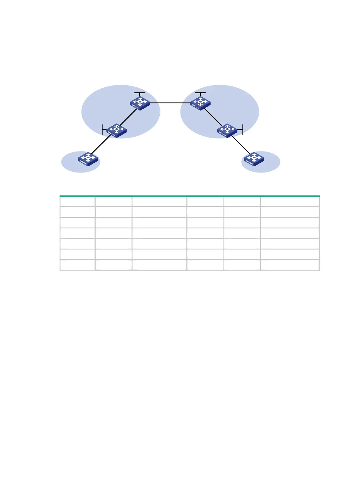
Figure 93 Network diagram
Table 35 Interface and IP address assignment
CE 1 Vlan-int10 100.1.1.1/24 ASBR 1 Loop0 192.2.2.2/32
PE 1 Loop0 192.1.1.1/32 Vlan-int23 23.1.1.2/24
Vlan-int23 23.1.1.1/24 Vlan-int26 26.2.2.2/24
PE 2 Loop0 192.4.4.4/32 ASBR 2 Loop0 192.3.3.3/32
Vlan-int22 22.2.2.1/24 Vlan-int26 26.2.2.3/24
CE 2 Vlan-int10 100.1.1.2/24 Vlan-int22 22.2.2.3/24
Configuration procedure
Before you perform the following configurations, configure VLANs and add ports to VLANs.
1. Configure CE 1.
<CE1> system-view
[CE1] vlan 10
[CE1-vlan10] quit
[CE1] interface vlan-interface 10
[CE1-Vlan-interface10] ip address 100.1.1.1 24
[CE1-Vlan-interface10] quit
[CE1] interface gigabitethernet 1/0/1
[CE1-GigabitEthernet1/0/1] port link-type trunk
[CE1-GigabitEthernet1/0/1] port trunk permit vlan 10
[CE1-GigabitEthernet1/0/1] quit
2. Configure PE 1:
# Configure an LSR ID.
<PE1> system-view
[PE1] interface loopback 0
[PE1-LoopBack0] ip address 192.1.1.1 32
[PE1-LoopBack0] quit
CE 1
PE 1
PE 2
ASBR 1 ASBR 2
CE 2
AS 100 AS 200
MPLS or IP
backbone
MPLS or IP
backbone
GE1/0/1
Vlan-int10
GE1/0/1
Vlan-int23
Vlan-int23
GE1/0/1
GE1/0/1
Vlan-int10
Vlan-int22
Vlan-int22
Vlan-int26
Vlan-int26
Loop0
Loop0
Loop0
Loop0
Site 1 Site 2

 Loading...


