391
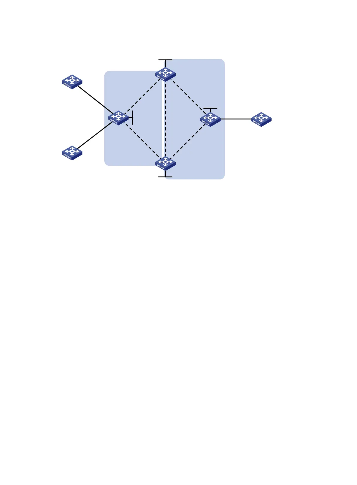
Figure 104 Network diagram
Configuration procedure
1. Configure an IGP and public tunnels on each PE. (Details not shown.)
2. Configure UPE:
# Configure basic MPLS.
<UPE> system-view
[UPE] interface loopback 0
[UPE-LoopBack0] ip address 1.1.1.1 32
[UPE-LoopBack0] quit
[UPE] mpls lsr-id 1.1.1.1
[UPE] mpls ldp
[UPE-ldp] quit
# Enable L2VPN.
[UPE] l2vpn enable
# Configure VSI aaa that uses LDP as the PW signaling protocol, and establish the primary PW
with NPE 1 and the backup PW to NPE 2.
[UPE] vsi aaa
[UPE-vsi-aaa] pwsignaling ldp
[UPE-vsi-aaa-ldp] peer 2.2.2.2 pw-id 500
[UPE-vsi-aaa-ldp-2.2.2.2-500] backup-peer 3.3.3.3 pw-id 500
[UPE-vsi-aaa-ldp-3.3.3.3-500-backup] quit
[UPE-vsi-aaa-ldp-2.2.2.2-500] quit
[UPE-vsi-aaa-ldp] quit
[UPE-vsi-aaa] quit
# Create VLAN 10 and assign GigabitEthernet 1/0/1 to the VLAN.
[UPE] vlan 10
[UPE-vlan10] port gigabitethernet 1/0/1
[UPE-vlan10] quit
# On interface GigabitEthernet 1/0/1 connected to CE 1, create an Ethernet service instance
and bind the Ethernet service instance to VSI aaa.
CE 3NPE
3
NPE 1
CE 1
CE
2
NPE 2
UPE
GE1
/
0/
1
VLAN 11
GE
1/
0
/2
VLAN 10
Vlan
-
int12
12.
1
.1
.
1/
24
Vlan
-int
13
13.
1.
1
.1
/24
Vlan-int16
16.1.1.1/24
Vlan-int15
15
.1
.
1.
1/24
GE
1/
0
/1
VLAN
10
Loop0
2
.
2
.
2
.2
/
32
Loop0
3
.3.
3.3
/32
Loop0
4.
4
.4
.4
/
32
Vlan-int16
16.1.1.2/24
Vlan
-
int15
15
.
1.
1.
2
/24
Vlan-int13
13.
1.
1.2/24
Vlan-
int12
12
.1
.1
.
2/
24
Loop0
1
.1.1.1/
32
Backbone
domain
Vlan-
int17
17
.1
.
1.
1/
24
Vlan-int17
17.
1.
1
.2
/24
Edge
domain

 Loading...


