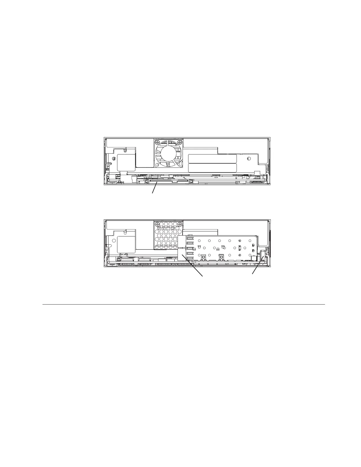
Rear View of the LTO Tape Drive
Figure 36 shows the connector locations on the drive.
Note: This view is of the connections on rear of the drive assembly, located inside
the 7226 Device Enclosure.
Note: Use only the lower Fibre Channel connector on the LTO5 Fibre Channel
Tape Drive as shown.
Note: Drive Power Connector P/N 45E3859 is used to connector the LTO5 Fibre
Channel Tape Drive power connector to the enclosure power connector.
Operating the LTO-5 Tape Drive
Operating the drive involves using the following front panel items:
v Single-character Display (SCD)
v SCD Dot
v Ready and Fault Status LEDs
v Unload Button
Operating Modes
The drive functions in the following modes:
v Operation mode - functions include reading and writing data, cartridge
manipulation, error reporting, and firmware updating using an field microcode
replacement (FMR) cartridge. For more information, see “Status LEDs” on page
68.
ROLG022-0
SAS connector
Fibre Channel
connector
Power
connector
LTO Fibre Channel Drive
LTO SAS Drive
Figure 36. Connector Locations on the Drive
Chapter 6. Half High LTO-5 Tape Drive 67

 Loading...