137
ifm Vision Assistant O3M
UK
15.2 Place and connect modules
► Click on .
> The "Logic" screen is displayed.
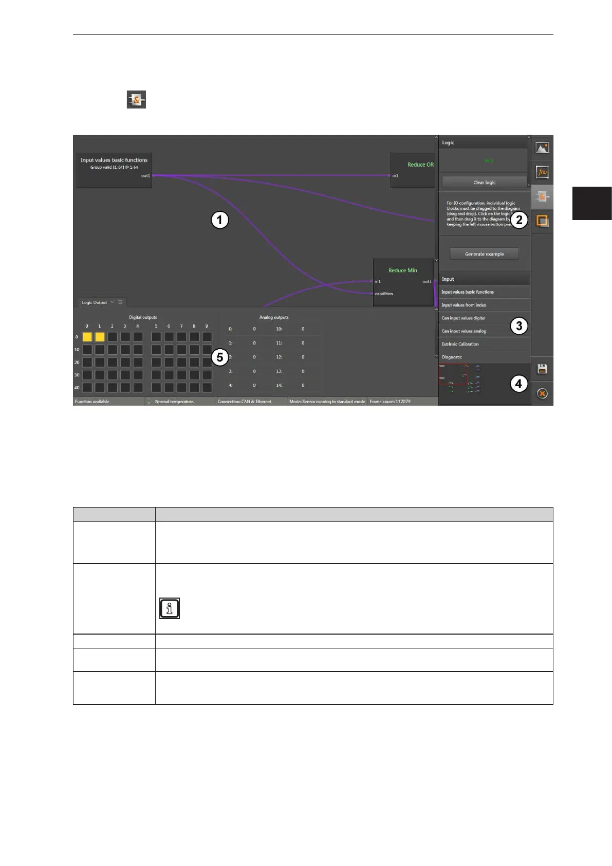
The logic editor is divided into five areas:
1: Main area
2: Information area
3: Selection area
4: Overview area
5: Result area
Window area Description
Main area
In the main area, the assignment of the input signals (sensor results) to the outputs is displayed. Input
signals, operators and outputs are shown as modules with different font colours. Lines between these
modules represent the connection. If the modules in the main area go beyond the visible area, this area
can be shifted using the scroll bar at the edge of the main area.
Information area
In the information area, the logic status is displayed. The status of the logic primarily indicates the memory
usage on the device.
The number of outputs used simultaneously is limited. An error message appears if modules with
further outputs are placed and the capacity is exceeded.
Selection area In the selection area, all input signals, operators and outputs are listed.
Overview area
In the overview area, a smaller version of the main area is displayed. If the modules in the main area go
beyond the visible area, this area can be shifted by dragging the red frame with the mouse.
Result area
The result area displays the status of the 100 digital and 20 analogue outputs. The status of the digital
outputs is indicated by colours: Colour "grey": "0" (false); Colour "yellow": "1" (true). Hovering over one of
the digital outputs opens a tooltip with the respective output number.


 To Next Page