143
ifm Vision Assistant O3M
UK
15.3.3 Example for "Analogue CAN input signals" module
In logic, the "Analogue CAN input signals" module is used to process the motion speed of a machine. The
calculated values are used to adjust the size of the warning range of the machine.
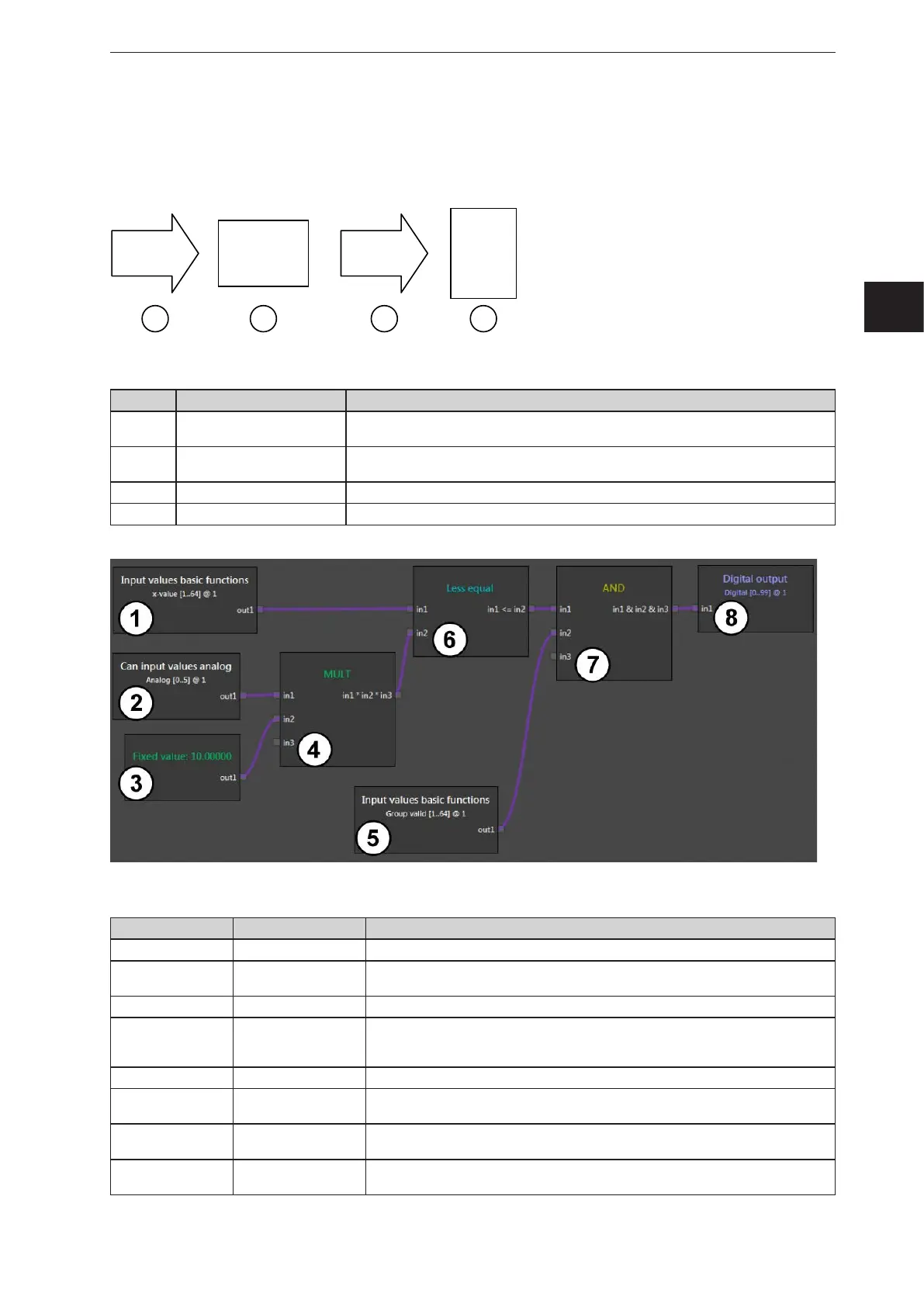
A programmable controller is connected to the device as follows:
2
PLC
3
CAN
4
O3M
1
INPUT
Description of the devices and interfaces used:
Number Function Description
1 Input value
The speed is applied as a scaling value to the analogue input of the programmable
controller (current or voltage).
2
Programmable controller
(e.g. CR0403)
The programmable controller converts the values to a 12-bit CAN value between
0...1 um.
3 CAN interface The CAN interface transmits the motion speed in 12-bit resolution.
4 Device (e.g. O3M251) The device uses the analogue input value to scale the warning range.
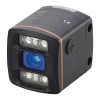
Description of the modules used in the example:
Module number Module Description
1 Basic function The x value is filtered out of ROI group 1.
2
Analogue CAN input
signals
The CAN input values from the controller are processed at analogue input 1.
Previously, the controller has scaled the values to the range 0...1.
3 Fixed value The fixed value "10" defines the maximum warning distance in metres.
4 MULT
The speed value is multiplied by the maximum warning distance. This calculates
the threshold value (warning value). The threshold value is dynamic (depending on
the speed at the analogue input).
5 Basic function The validity of ROI group 1 is checked.
6 Less than or equal
It is checked whether the current measured distance value is less than or equal to
(<=) the speed-dependent warning value.
7 AND
If the measurement is valid (module 5) and the measured distance value <= the
warning value (module 6), a "1" is provided.
8 Digital output
Digital output 1 applies the binary information to the CAN output. The value is
provided via the controller as a physical output.