61
ifm Vision Assistant O3M
UK
9.4 Position of the device
The following describes how the position of the device is indicated in the ifm Vision Assistant.
The following explanations refer to a reference surface to which the device is oriented. For
vehicles, the reference surface is, in most cases, the road surface. A wall or a virtual plane can be
selected as reference surface.
The sensor orientation determines the installation of the device:
● vertical to the surface (portrait format)
● horizontal to the surface (landscape format)
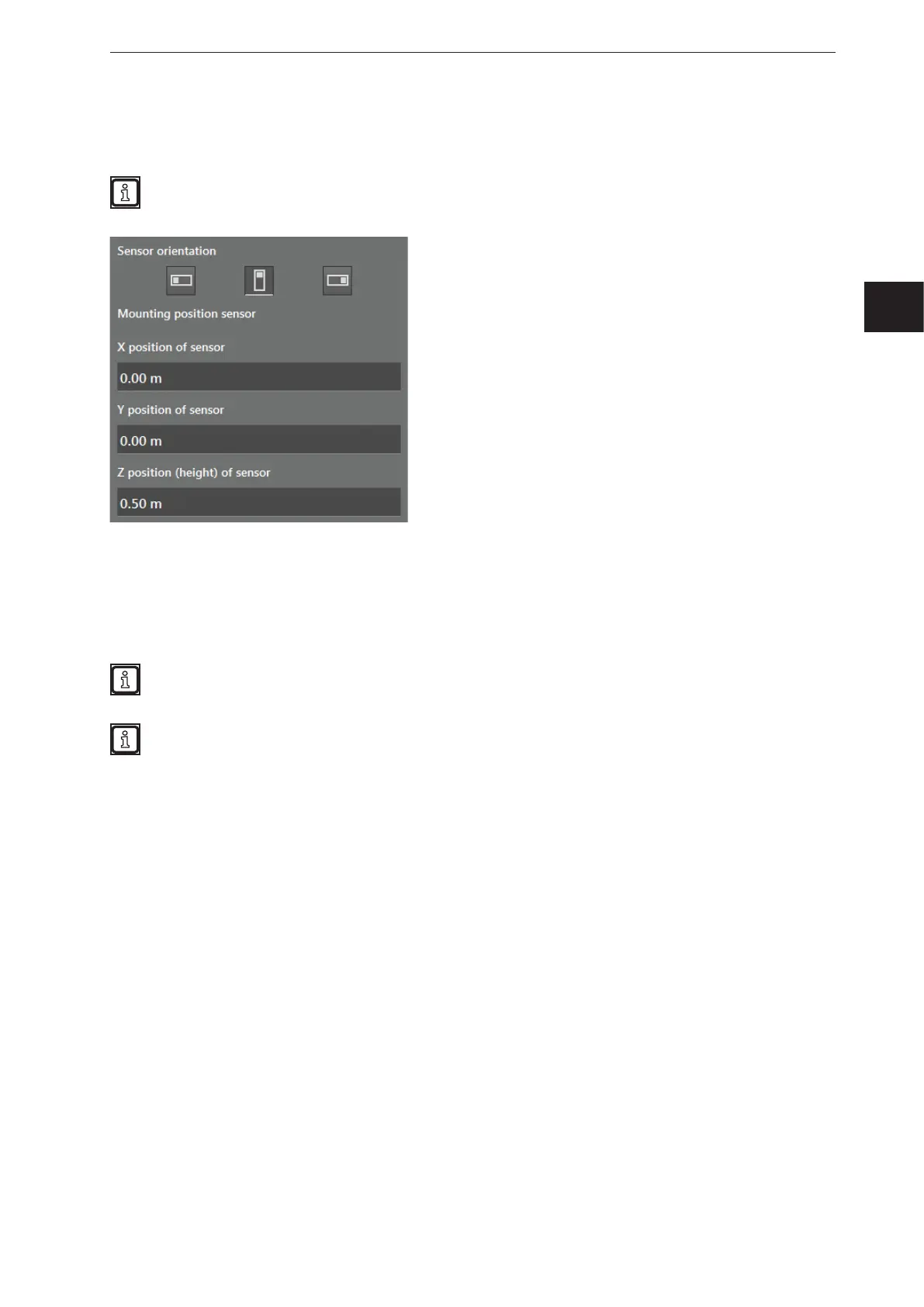
The pictograms in the figure indicate the position of the device (view from the front).
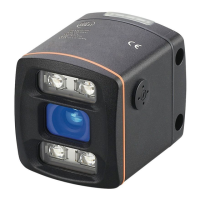
Please consider the position of sensor screen when orienting the sensor. In the figure above, the
sensor screen is marked with a dot.
If none of the pictograms corresponds with the mounted device, please chose the pictogram that
looks most similar. The precise adjustment can be carried out later.
In this section, the reference surface is parallel to the X/Y level. The position of the reference point is
described in chapter 9.3.
With the fields "X position of sensor" and "Y position of sensor", the device can be relocated in the world
coordinate system. Due to this, the coordinate origin can be relocated to a point that is most adequate for
the application. Since the 3D coordinates of the device are provided in this world coordinate system, in
most cases, no further calculation is necessary.
In the field "Z position (height) of the sensor", the position of the device is indicated on the Z axis. The Z
axis is vertical to the reference surface. The Z position indicates the mounting height of the device.


 To Next Page