ifm Vision Assistant O3M
170
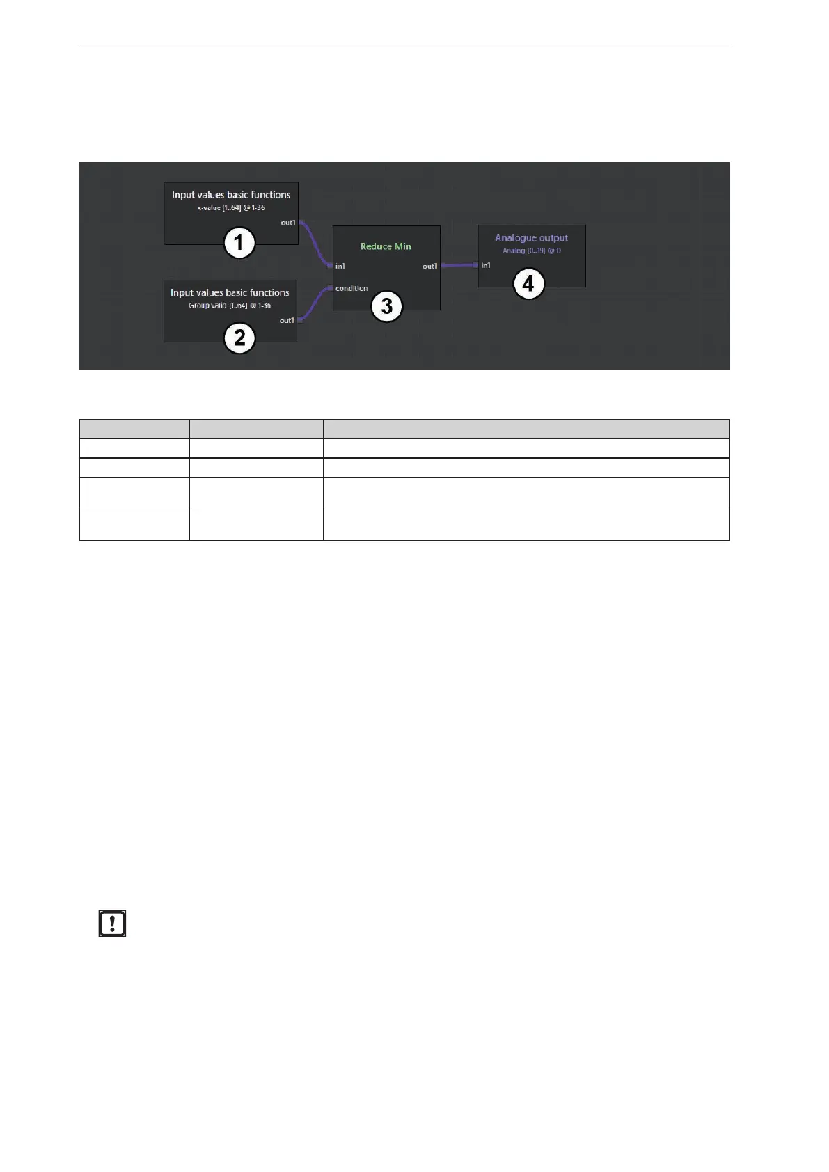
15.11.1 Example for the "Vector Min" module
The "Vector Min" module checks the validity of the x-values at input "in1". Then the smallest x-value is
determined from the x-values and output at analogue output 0.
Description of the modules used in the example:
Module number Module Description
1 Basic function The "Basic function" module filters out the x-values.
2 Basic function The "Basic function" module checks the validity of the x-values.
3 Vector Min
The "Vector Min" module processes the x-values at input "in1" and the validity at
input "Condition". The smallest x-value is then determined from the x-values.
4 Analogue output
The smallest x value is provided as a numerical single value at analogue output
0.
15.12 Description of the "Output" modules
The "Output" selection area displays functions for outputting digital and analogue signals.
The following modules are available:
● Digital output
● Analogue output
15.12.1 "Digital output" module
The "Digital output" module transfers the binary results from the logic editor to the connected peripherals.
A maximum of 100 binary outputs are available. The "in1" input processes single binary values or vectors.
The results are available at the following interfaces:
● Ethernet (UDP) (→ „16.3.1 Ethernet (UDP)“)
● CAN (J1939, CANOpen) (→ „16.3.2 CAN (J1939, CANOpen)“)
● Internal for configuring the 2D overlay (→ „11 2D overlay“): Output binary results via text replacement
within the 2D overlay (→ „11.2.1 Add text“)
When using the DI firmware in combination with the "Logic output" colour mode
(→ „11.4.1 Visualising 3D ROIs as a moving wall“): The indices set in the output must
correspond to the numbers of the ROI groups.


 To Next Page