ifm Vision Assistant O3M
8
3 Installation
3.1 Hardware
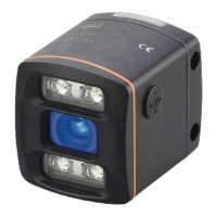
The mobile 3D sensor is operated as a system together with the illumination unit.
During installation note the following:
► Operate sensor and illumination unit in conjunction.
► Install sensor and illumination unit between 0 and 2.80 m
apart.
> Select the matching MCI connection cable depending on
the distance.
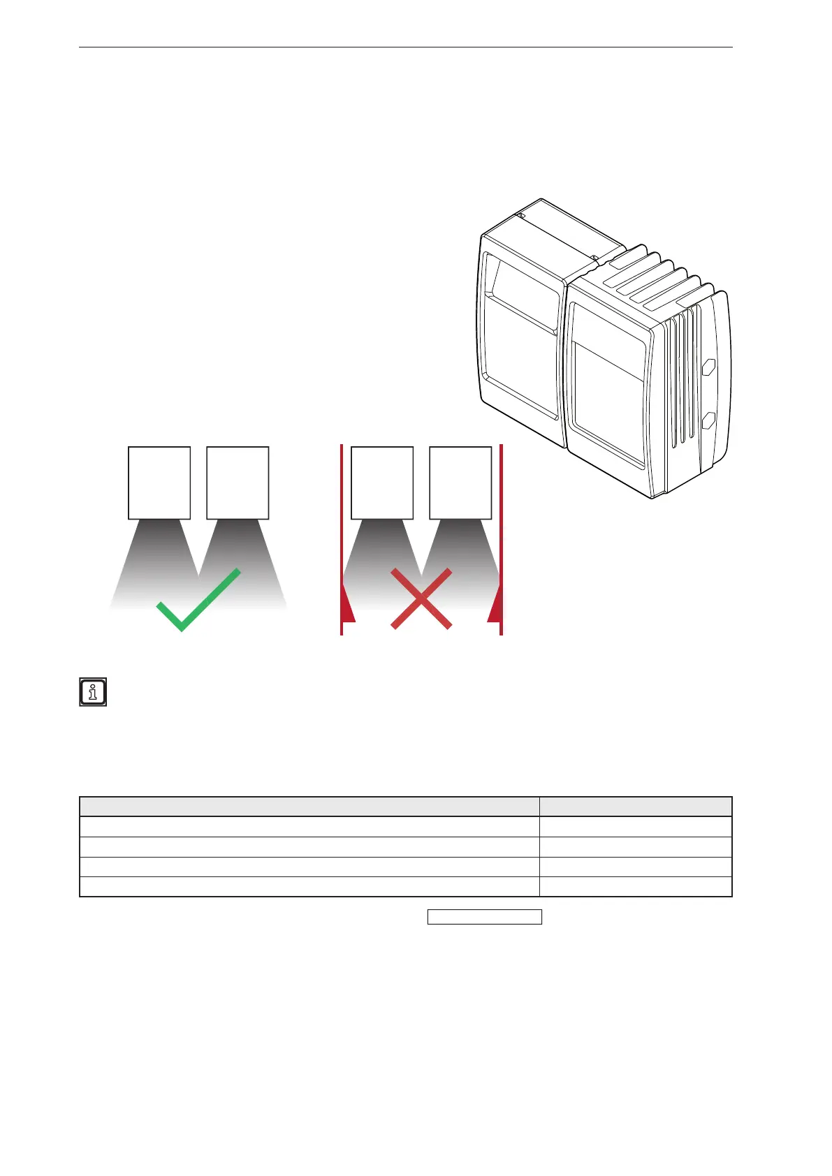
► Keep the area illuminated by the illumination unit free from
any obstructions in a close range (up to 50 cm)
(see figure below).
► Use cables with strain relief.
Sensor Illumination
unit
Sensor Illumination
unit
Further information about the electrical connection and the correct pin connection
→ Short instructions or operating instructions.
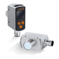
3.2 Mounting accessories
Depending on the intended mounting location and the type of installation, the following mounting
accessories are available:
Description Art. no.
Mounting set "U-tube" (u-shaped fixture with adjustment options for O3Mxxx housings) E3M100
Mounting set for rod mounting Ø 14 mm (clamp and bracket for O3Mxxx housings) E3M103
Rod, angled Ø 14 mm, length 130 mm, M12 E20939
Rod, angled Ø 14 mm, length 200 mm, M12 E20941
You can find more information about the accessories at:
www.ifm.com