ifm Vision Assistant O3M
174
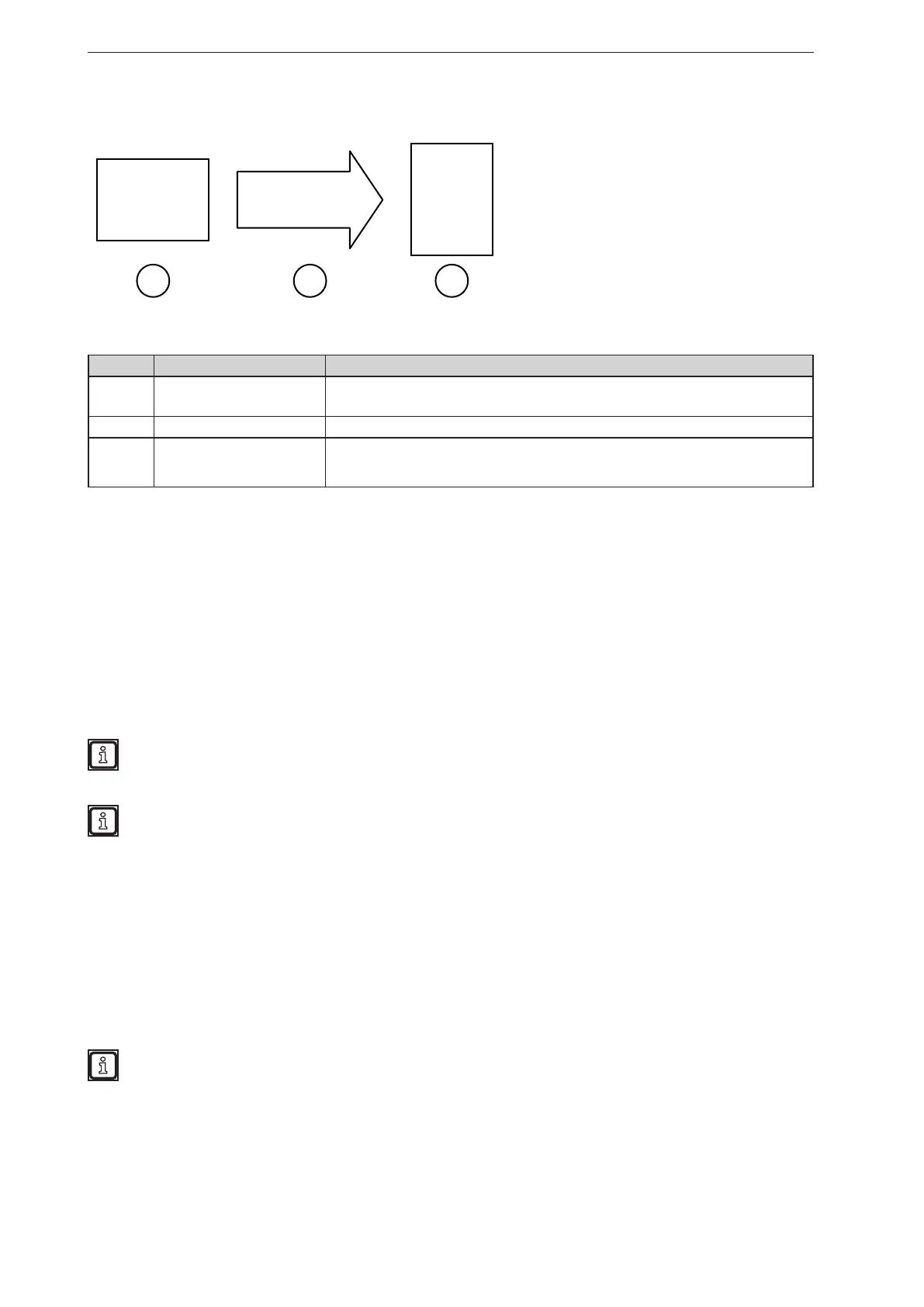
A programmable controller is connected to the device as follows:
1 2 3
O3M CAN PLC
Description of the devices and interfaces used:
Number Function Description
1
Programmable controller
(e.g. CR0403)
The programmable controller converts the 12-bit CAN value to a physical output.
2 CAN interface The CAN interface transmits the analogue value (distance) in 12-bit resolution.
3 Device (e.g. O3M251)
The device returns the analogue output value. The output values (distance) are scaled
to the value range 0..1 ("0" corresponds to a distance of ≤ 0 m, "1" corresponds to a
distance of ≥ 10 m).
15.13 Description of the switches "Enable CAN output"
In the "Enable CAN output" selection area, switches for signal transmission via the CAN interface are
displayed. To keep the bus load low, a maximum of 3 CAN messages (size: 64 bits) are sent. The
switches each activate one of the CAN messages.
Each switch activates a fixed set of outputs:
● Switch 1: digital 0 - 37 and analoge 0 - 1
● Switch 2: digital 38-99
● Switch 3: analogue 2-5
Keep the bus load of the CAN interface as low as possible.
► Only activate the necessary digital or analogue outputs via one of the switches.
The CAN interface is described in a separate CAN document.
15.14 Description of the "Logic teach commands"
In the "Logic teach commands" selection area, commands for triggering and deleting signals are
displayed.
The "Logic teach commands" simulate a signal for storing information with the "Teach" module:
● [Teach] button: The signal for storing information with the "Teach" module is triggered.
● [Reset] button: The memory contents of the "Teach" module are deleted.
The "Logic teach commands" can be found at the end of the selection list
(→ „15.2 Place and connect modules“).


 To Next Page