3 Device AGP MotherBoard Design
3-14
Intel740™ Graphics Accelerator Design Guide
3.2.3.3 Assumptions for Board Design Guidelines
These guidelines are primarily for Accelerated Graphics Port (AGP) designs that use an Intel740
graphics controllers on a 82443BX motherboard and an AGP-compliant add-in card. They assume
certain requirements in order to produce an AGP compliant placement and routing solution. These
assumptions were used for the initial pre-route analysis of the design.
3.2.3.4 Add-in Card guideline assumptions:
All of the data line lengths within a group of signals needed to be within ±0.5 inches of their
associated strobe. The board impedance needed to be in the range of 50Ω to 85Ω. This range is
used to cover design targets and manufacturing tolerances.
Because crosstalk is a large component of skew, it was necessary to specify board routing. All
traces needed to be routed with a separation of two times the trace width (6:12). Additionally, all
lines within a group needed to be of the same type (microstrip or stripline). This is because
microstrip (surface traces) and striplines (buried traces) have different propagation velocities, and
mixing these can increase the flight time skew beyond acceptable limits. All the traces on the
plugin card provided to us were routed as microstrip.
* The clock trace on the add-in card shall be routed to achieve an interconnect delay of 0.6ns ±
0.1ns as determined from trace length and trace velocity.
3.2.3.5 Motherboard Guideline Assumptions
Data Signal and Strobe Requirements
The motherboard needed to have an impedance range of 50Ω to 80Ω (as recommended by the
82443BX design guide). This range was used to cover design targets and manufacturing tolerances.
The maximum line lengths are dependent on the type of trace and the amount of coupling.
The maximum line length was dependent on the routing rules used on the motherboard. These
routing rules were created to give freedom for designs by making tradeoffs between signal
coupling (trace spacing) and line lengths. These routing rules assumed trace spacings of 1:2 (5:10
mils). Trace spacing refers to the distance between the traces as being the twice the width of the
trace.
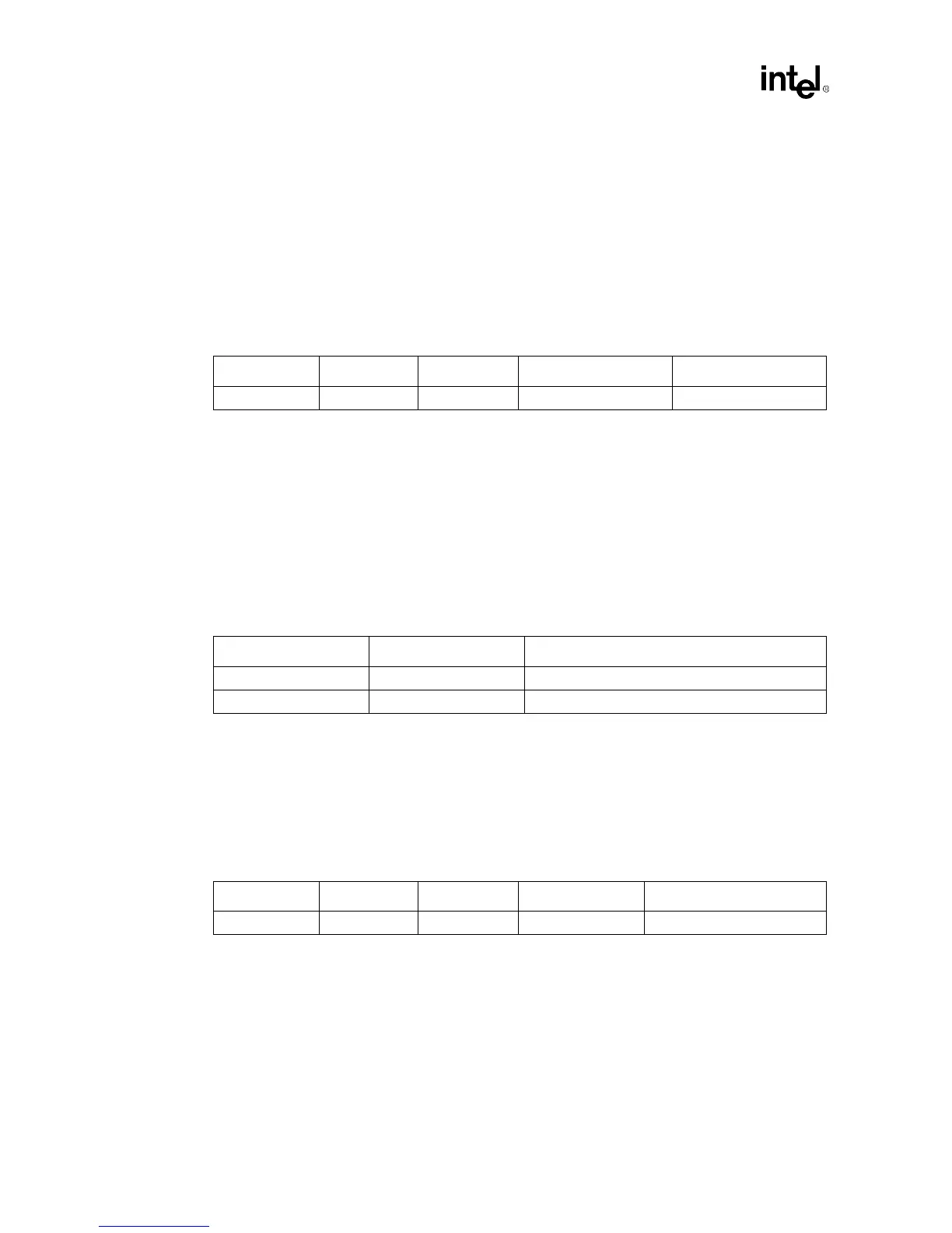
Table 3-4. Data Signal and Strobe Guideline Assumptions
Width:Space Zo Trace Line Length Line Length Matching
1:2 50
Ω
to 85
Ω
Data / Strobe 0.0in < line length < 3.0 in Strobe
±
0.5 in of group
Table 3-5. Control and Clock Signal Guideline Assumptions
Trace Width:Space Line length
Control signals 1:2 0 < line length < 3.0
Clock 1:4 0.6ns
±
0.1ns *
Table 3-6. Data signal and strobe requirements
Width:Space Zo Trace Line Length Line Length Matching
1:2 50
Ω
to 80
Ω
Data / Strobe follow topologies strobe longest signal of group