Revision 0.91
9
SO-DIMM Module — Unbuffered SDRAM/SGRAM Graphics
6.0 Address Translation
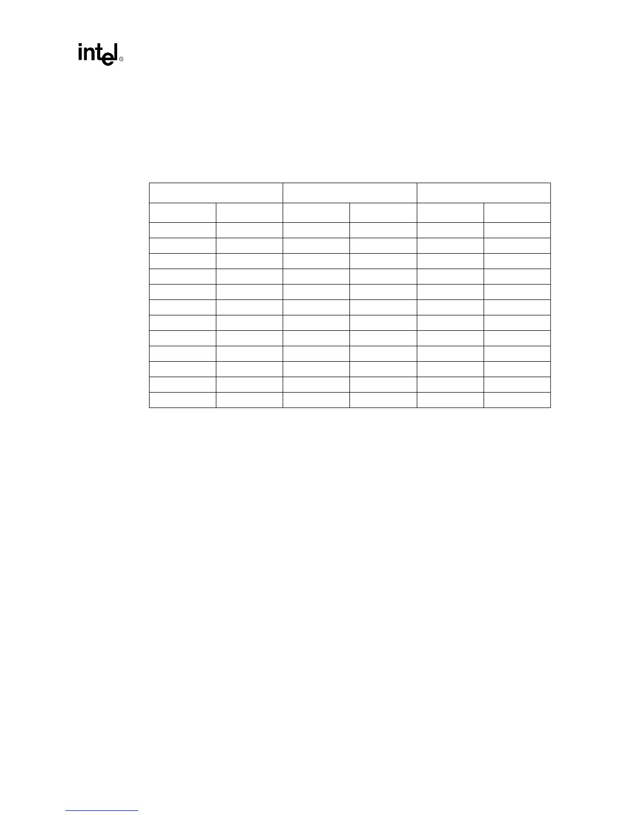
Table 3 should be followed for 256Kx32 and 512Kx32 SGRAM devices. This table specifies the
SGRAM device to SO-DIMM connector connections for a 256Kx32 and 512Kx32 devices.
NOTES:
1. The names for pin 80, 81 and 82 are different for 256Kx32 and 512Kx32 device connection.
2. SO-DIMM’s pin 80 (which is labeled as A10) is a no connect for 256Kx32 device and is connected to pin 30
(labeled as A8) of 512Kx32 device.
3. SO-DIMM’s pin 81 (which is labeled as A9) is connected to pin 29 (labeled as A9/BA) of 256Kx32 device and
is connected to pin 29 (labeled as A10/BA) of 512Kx32 device
4. SO-DIMM’s pin 82 (which is labeled as A8) is connected to pin 51 (labeled as A8/BA) of 256Kx32 device and
is connected to pin 51 (labeled as A9/AP) of 512Kx32 device.
6.1 Configuration
Graphic controllers can determine the module capabilities one of three ways; they are:
•
Using the default parameters with power-up testing
•
Using resistor strapping options on the data lines
•
Using an optional Serial Presence Detect EEPROM
Modules are required to include resistor support (3 resistors); the Serial Presence Detect EEPROM
is optional.
6.2 Default Parameters
All memory modules must meets these baseline component requirements.
Table 3. Address Translation
SODIMM 256Kx32 512Kx32
Pin # Functionality Pin # Functionality Pin # Functionality
92 A0 31 A0 31 A0
91 A1 32 A1 32 A1
90 A2 33 A2 33 A2
89 A3 34 A3 34 A3
88 A4 47 A4 47 A4
87 A5 48 A5 48 A5
84 A6 49 A6 49 A6
83 A7 50 A7 50 A7
82 A8 51 A8/AP 51 A9/AP
81 A9 29 A9/BA 29 A10/BA
80 A10 No Connect No Connect 30 A8
79 A11/Reserved No Connect No Connect No Connect No Connect