Intel740™ Graphics Accelerator Thermal Design Considerations
12 Application Note 653
4.2.2.2 Low Profile Fan Heat Sink Electrical Requirements
The Fan Heat Sink’s total maximum power usage should not exceed 1 Watt and should start and
operate within ±10% of rated voltage.
The Fan Heat Sink may use a connector which incorporates 2 separate connections: 12 Volt power,
ground and signal (tachometer function). The fan connector may mate with a receptacle attached to
a power cable that will be installed by the graphics card manufacturer. See Figure 5.
The Fan Heat Sink assembly, when installed in at least one typical host application, should not
cause an increase in emissions above that measured from the host application before the assembly
was installed.
The signal pin on fan header may supply an open collector rotor lock output signal:
• Operating: Output is asserted by pulling the output low
• Locked Rotor: Output is de-asserted, allowing output to float high using a pull up resistor on
the graphics card.
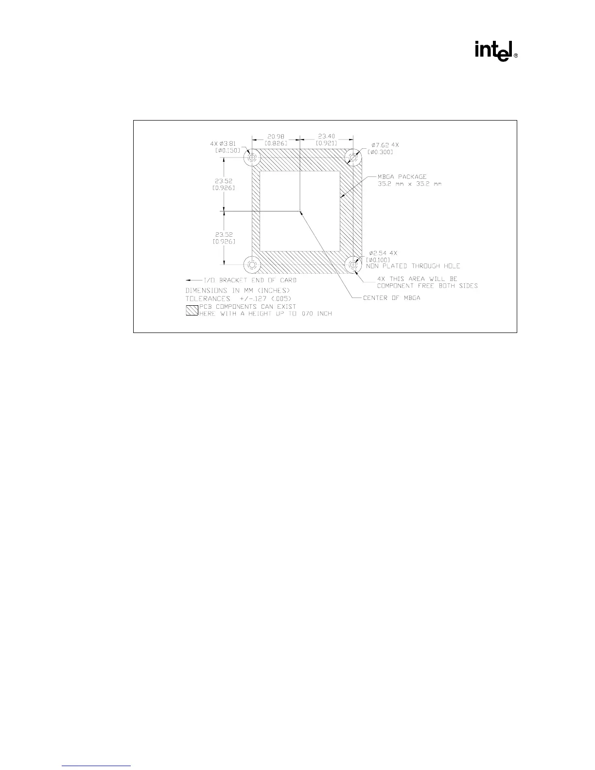
Figure 5. PCB Layout Guidelines for Mounting Holes