Intel740™ Graphics Accelerator Design Guide
3-19
3 Device AGP MotherBoard Design
Table 3-11. Memory Layout Restrictions (See Figure 3-16 and Figure 3-17)
Signal Intel740™ to SGRAM Stub SGRAM Stub
Min Max Min Max
MA[11:0] .25’’ 4.9” 0.25" 0.6”
MD[63:0], DQM[7:0] .25’’ 3.9” 0.25" 0.4”
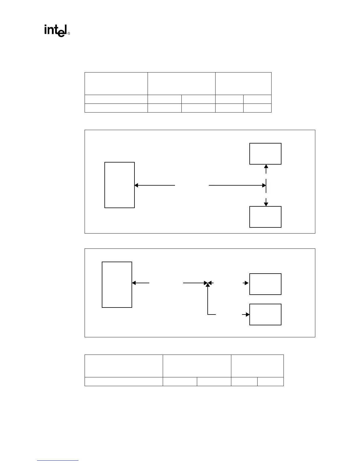
Figure 3-16. Layout Dimensions (MA[11:0])
Figure 3-17. Layout Dimensions (MD[63:0], DQM[7:0])
Table 3-12. Memory Layout Restrictions (See Table 3-16 and Table 3-17)
Signal Intel740™ to SGRAM Stub SGRAM Stub
Min Max Min Max
WEA#, SRASA#, SCASA#, CSA0# 2.25’’ 4.9” 0.25’’ 0.6’’
Intel740™
Chip
0.25" - 4.9"
SGRAM
SGRAM
0.25" - 0.6"
0.25" - 0.6"
Intel740™
Chip
0.25" - 3.9"
SGRAM
SGRAM
0.25" - 0.6"
0.25" - 0.4"