Intel740™ Graphics Accelerator Design Guide
2-3
Addin Card Design
2.1.2 BT829B - Video Decoder
The Bt829B is a video capture processor used to convert analog video data into CCIR 601 digital
video data. This chip contains the following capabilities.
•
Analog Inputs. The Bt829B contains four composite video inputs along with one chroma and
one luma input for s-video.
•
I
2
C Interface. Control of the Bt829B is accomplished though the use of an I
2
C interface. All
of the chip’s registers are programmed using this interface as is the selection of the analog
input source to use in generating digital video data.
•
Video Port. The Bt829B contains a video port capable of outputting 8 or 16 bit data. The data
format is YUV 4:2:2 with HSYNC, VSYNC, and PIXEL CLOCK as control signals.
2.1.2.1 BT869 - TV Encoder
The Bt869 provides high quality TV out. This component contains the following interfaces:
•
Input Port. The Bt869 is capable of receiving data in two formats. The format used by this
reference design for receiving data is through the 24 bit digital port accepting data on both
edges of the reference clock. This mode of operation is documented in the Intel740™
Graphics Accelerator Datasheet. The second method for capturing data is through the use of
the VMI protocol. This interface is documented in the VMI 1.4 Interface Specification.
•
Flicker Filter Output. The output of the Bt869 is a very high quality flicker filtered output.
This is due to a 5 tap internal filter. Output can be displayed in interlaced, non-interlaced,
PAL, or NTSC formats. Macrovision7 output is also supported in the Bt869 component. The
Bt869 is capable of displaying composite or S-Video data.
•
I
2
C Interface. Control of the Bt869 is achieved through the I
2
C port.
2.1.3 Terminology
2.1.3.1 Power Sources
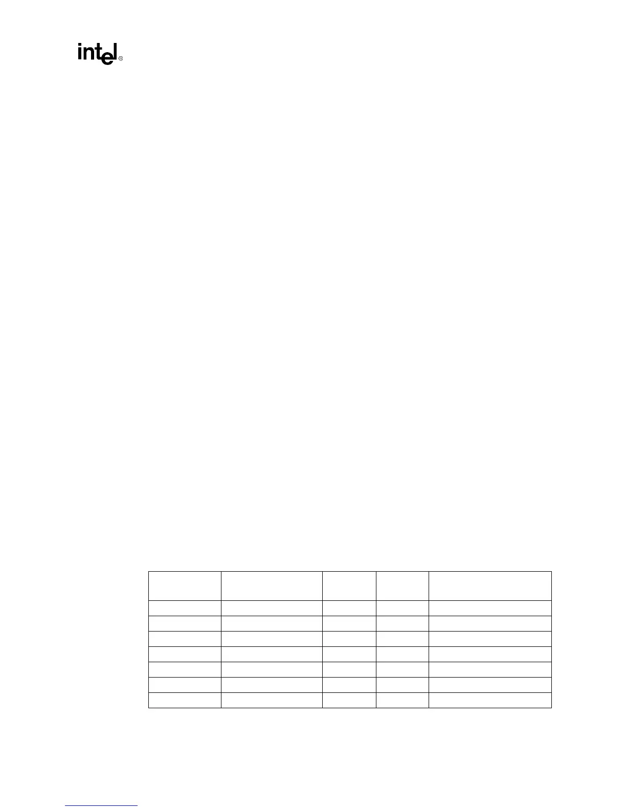
The card is supplied with four voltages through the edge connector. Other voltages are derived on-
board. Thus, the Power Layer of the board must be divided into several distinct planes. Table 2-2
lists the various power elements on the Intel740™ graphics accelerator reference design. Each of
the voltage sources are supplied by a plane except for 12 volts, which is supplied by a 25 mil trace.
Table 2-2. Intel740™ Graphics Accelerator Power Supplies
Schematic
Symbol
Description Voltage
Max
Current
Source
VDDQ3 3.3V AGP Supply +3.3V 8.0A Edge connector
VCC3 3.3V Logic Supply +3.3V 6.0A Edge connector
VCC 5V Logic Supply +5.0V 2.0A Edge connector
+12V 12V Supply +12V 1.0A Edge connector
VCC2 2.7V Core Supply +2.7V 3.0A VCC3, via Voltage Regulator
3VAA_BT869 3.3V Analog Supply +3.3V < 1.0A VCC3, via Ferrite Bead
AVCC 5V Analog Supply +5.0V < 1.0A VCC, via “fence”