Application Note 1
1.0 Introduction
For the 3 Device AGP down motherboard design discussed in the Intel740™ Graphics Accelerator
Design Guide, Rev 3 (order number 290619), both the video BIOS and support for the 3 Device
AGP low power logic must be integrated into the system BIOS. This document details the needed
changes to system BIOS to implement the low power logic. Details to incorporate the video BIOS
in the system BIOS is beyond the scope of this document.
The on-board AGP device and the AGP add-in card will not be active simultaneously. If an add-in
card is present in the AGP slot, the on-board AGP graphics device remains disabled. The system
BIOS will provide support for single monitor or multimonitor configurations with or without an
AGP graphic device active. The latter is achieved through a CMOS option that will allow the end
user, system integrator, or OEM to manually disable the on board Intel740 chip and bypass any
enabling events.
2.0 Low Power Mode Overview
Two signals, GPO27# and GPO28#, from the PIIX4E are used in this design. These GPOx signals
must be asserted by the system BIOS.
GPO28# is needed to put the Intel740 chip in low power mode. This signal must be asserted
sometime after the trailing edge of system RESET (See Figure 2).
GPO27# serves as the hardware reset for the Intel740 chip. A hardware reset to the Intel740 chip
takes the device out of the low power state. Since the PCIRST# signal is used to disable the device,
it can not be used for this purpose. At the trailing edge of GPO27# the Intel740 chip will be
functional (See Figure 1).
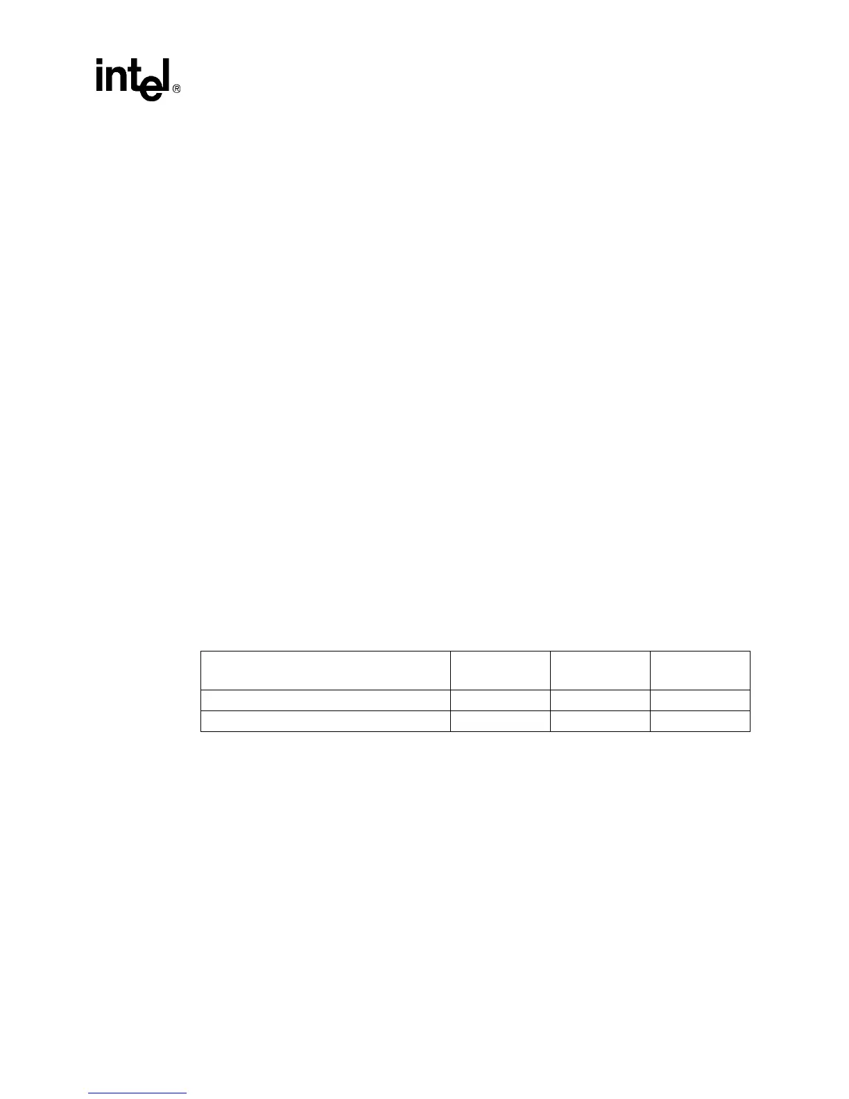
The duration of GPO28# and GPO27# are listed in Table 1.
NOTE:
1. 1 ms is the smallest system BIOS increment of time
2. SUM = The sum of the propagation delaly for the logic depicted in Figure 2.
Table 1. Signal Duration of the GPO Signals from PIIX4
Signal Active
Minimum
Duration
Actual Duration*
GP027# from PIIX4 Low (0) 1ms 1ms
GP028# from PIIX4 Low (0) =SUM 1ms