Intel740™ Graphics Accelerator Design Guide
3-15
3 Device AGP MotherBoard Design
Longer lines have more crosstalk, therefore longer line lengths require a greater amount of spacing
between traces to maintain skew timings
We assumed a 4 layer boardstackup as described earlier.
Control Signal and Clock Requirements
Some of the control signals require pull-up resistors to be installed on the motherboard. The stub to
these pull-up resistors needs to be controlled. Stubs to pull-up resistors need to be kept as short as
possible to avoid signal quality issues.
The clock lines on both the motherboard and the add-in card can couple with other traces. It is
recommended that the clock spacing (air gap) be at least two times the trace width to any other
traces. It is also strongly recommended that the clock spacing be at least four times the trace width
to any strobes. The motherboard needs to be designed to the type of clock driver that is being used
and motherboard trace topology.
Clock Line Matching
Skew between each AGP master clock input and the AGP target (chipset) must be within the 1ns
limit called out in the AGP specification. The driver use on this design can have up to 0.25ns of
skew from output to output. This means that propagation delays and settling time skews cannot
exceed 0.75 ns. Thus, for a single clock driver solution not only must each of the two clock trace
segments be balanced in such a way that signal quality is acceptable, but the trace segments must
be tuned in such a way as to meet the AGP specified skew requirements.
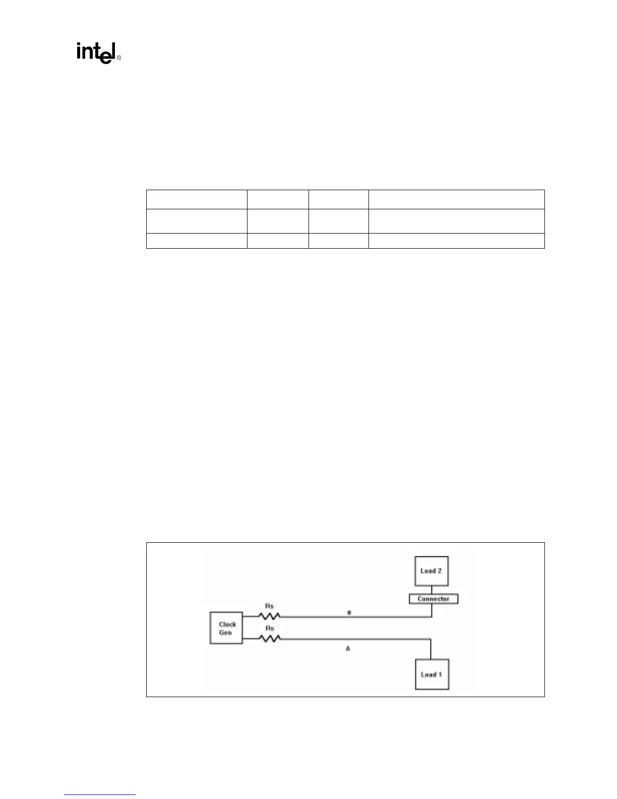
The clock topology used are shown in Figure 3-10.
Figure 3-10 shows the clock topology if three clock outputs are available. Each clock is a direct
connection to it's respective load. Here the trace segments A and B must be balanced with respect
to the target device clock trace in such a way as to meet system clock skew requirements.
Table 3-7. Control Signal Line Length Requirements
Trace Board Width:Space Line length
Control signals Motherboard 1:2
Follow lengths and topology for the data and
strobe signals.
Clock Motherboard 1:4 Length determined by clock skew matching.
Figure 3-10. Point-to-Point Topology