Intel740™ Graphics Accelerator 3 Device AGP System BIOS Design Guidelines
2 Application Note
2.1 State Diagrams
At system RESET, the Intel740™ graphics controller on the motherboard is always put into the
low power state. The following are examples in which the on-board device shall remain in low
power state:
1. AGP add-in card is present
2. PCI or ISA graphics device is the primary and only graphics device desired
3. Multimonitor configurations not utilizing the on-board graphics device
For example 2 and 3 above, an option should be provided in system BIOS or CMOS setup to keep
the Intel740™ chip in low power mode.
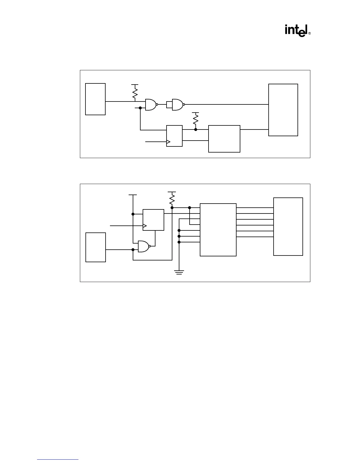
Note: When not in use, both GPO27# and GPO28# should be driven high (1).
Figure 1. Schematic Diagram for GPO27#
PIIX4E
PCIRST#
GPO27#
Vcc3
D
Q
Q#
PCICLK3
Vcc3
OE#
IN1 OUT1
ROMA16
RESET
Intel740™
Chip
4.7 KΩ
4.7 KΩ
Figure 2. Schematic Diagram for GPO28#
PIIX4E
Vcc3
D
Q
CLR#
Intel740™
Chip
GPO28#
SYSCLK
OE#
IN1
IN2
IN3
IN4
IN5
IN6
OUT1
OUT2
OUT3
OUT4
OUT5
OUT6
Vcc3
TEST
WEB#
SCASB#
SRASB#
CS0B#
CS1B#
2.2 KΩ