Addin Card Design
2-12
Intel740™ Graphics Accelerator Design Guide
2.2.5.1 Ground Planes
The Bt829B and associated circuitry have two ground planes, GND and ANALOG_GND
(AGND). These are electrically the same plane but should be separated by a fence, as described in
Section 2.1.3.2, “Fences” on page 2-4. The schematic illustrates which pins attach to which plane
as does Table 2-3. The opening in the fence should be under the Bt829B and be up to 75% of the
IC’s width. The AGND plane is the isolated or subset plane, hence GND is the return path for
current. The AGND plane should be as small as possible.
2.2.5.2 Power Planes
The Bt829 and associated circuitry have three power planes, VCC3, VCC and AVCC. The latter
two are digital and analog +5V, respectively. As above, these are electrically the same plane but
separated by a fence. This fence and the AVCC plane should parallel the AGND fence and plane
closely, with the opening in about the same location.
2.2.5.3 Passive Components and Signal Routing
All passive components should be placed as near to the Bt829B as possible. These parts include:
the 0.1µF and 0.01µF bypass capacitors, the 10µF capacitors, the 75 ohm terminating resistors, and
the crystal oscillator circuitry.
Note: There must be NO digital signals routed under or above the analog power and ground planes
(AVCC and AGND).
The filter circuits on the four video input signals (TUNER, SV_LUM, SV_CHR, CV_IN) need to
be located near the 50-pin connector. Note that other designs not using a 50 pin video connector
should have the filter circuits placed as close as possible to the input connectors. The analog traces
should not be routed such that they parallel other analog signals at a close spacing for a long length.
Wherever analog signals run in parallel, separated by less than 15 mils for longer than 250 mils,
run a ground line between them of approximately 12 mils width.
2.2.6 Bt869 Video Encoder
Note: Rockwell Semiconductor should be contacted for up to date layout recommendations.
2.2.6.1 Ground Planes
Only one ground plane is recommended for the Bt869. This ground plane should be formed as a
fence underneath the Bt869.
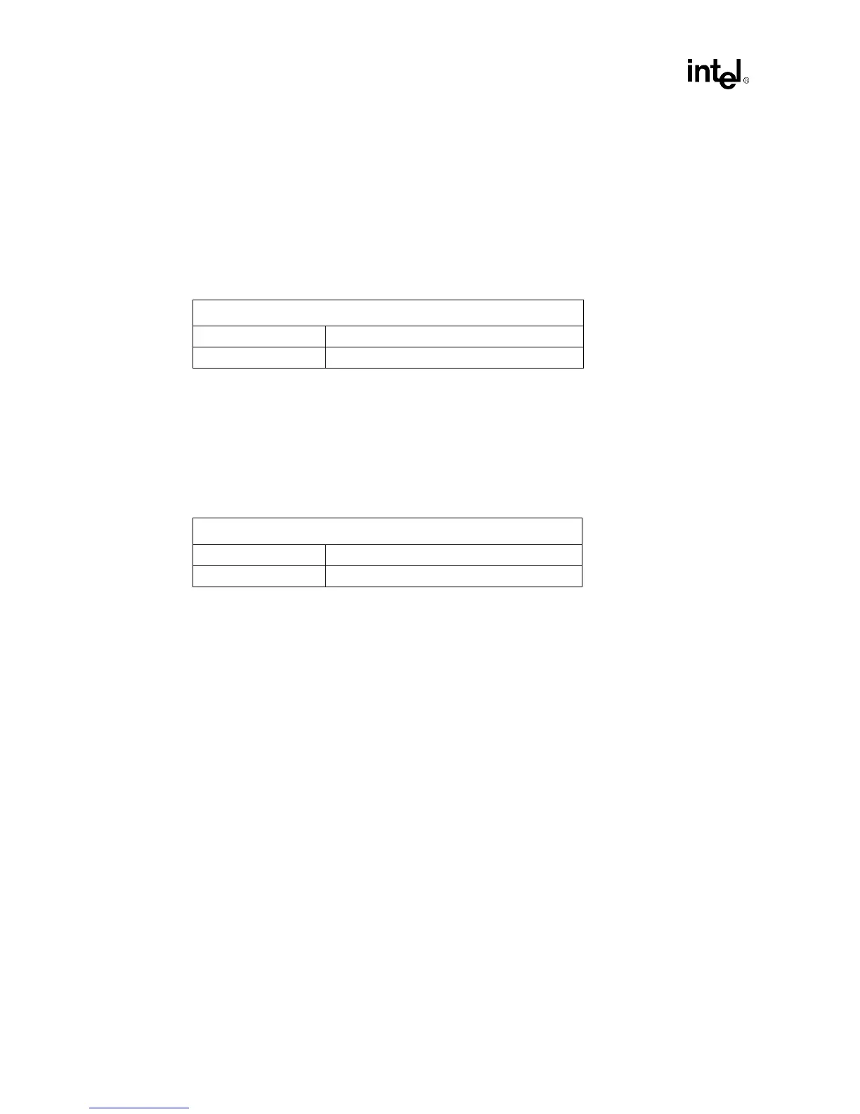
Table 2-3. Bt829B GND and AGND Pins
Bt829 Ground Pins
GND 11, 21, 31, 33, 39, 77, 81, 90, 93, 95, 100
AGND 42, 47, 54, 56, 58, 61, 66, 71, 75
Table 2-4. Bt829B VCC and AVCC Pins
Bt829B 5V Pins
VCC 10, 38, 76, 88, 96
AVCC 40, 44, 48, 60, 65, 72