Application Note 653 11
Intel740™ Graphics Accelerator Thermal Design Considerations
4.2.2 Low Profile Fan Heat Sink
A generic drawing for this Fan Heat Sink is shown in Figure 4. Recommended sources for the Low
Profile Fan Heat Sink are discussed in Appendix A, “Sources”.
The thermal performance of the Fan Heat Sink and Thermal Interface Material (combined) must be
sufficient to maintain a case temperature at or below T
case-hs
(See Table 1) in a worst case system
environment (defined as: zero airflow, 55°C ambient temperature).
Note: The weight of the Fan Heat Sink must not exceed 55 gm.
4.2.2.1 Low Profile Fan Heat Sink PCB Layout Guidelines
As the Low Profile Fan Heat Sink uses a mechanical attach, mounting holes must be provided in
the PCB to accommodate the clips necessary in attaching the Fan Heat Sink. PCB Guidelines for
the Fan Heat Sink mounting hole layout are provided in Figure 5. The mounting holes must be non-
plated, but each must have a grounding pad on the solder side of the board surrounding the hole. It
must be designed in such a way to ensure that the mechanical attachment clip is in solid contact
with this pad. The mechanical assembly should only contact the PCB within the four 0.300 inch
diameter component keep-out zones as shown in Figure 5. The outline of the Fan Heat Sink should
be silk-screened onto the PCB to facilitate placement of the Fan Heat Sink on to the package.
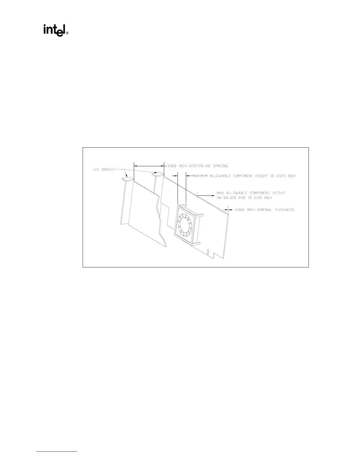
Figure 4. Low Profile Fan Heat Sink Drawing