Addin Card Design
2-6
Intel740™ Graphics Accelerator Design Guide
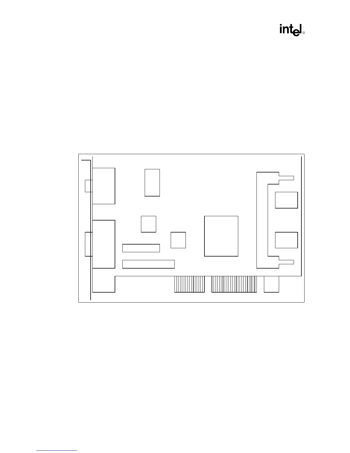
An example of the proposed component placement for an ATX form factor design is shown in
Figure 2-4. This is the placement used on the reference card. For NLX placement issues, refer to
Section 5.6, “NLX Considerations” on page 5-5.
ATX Form Factor:
•
The example placement (Figure 2-4) shows the Bt829B, Bt869, SO-DIMM Module, Intel740
graphics accelerator, VMI Port connections along with a 50 pin video connector.
•
The trace length limitation between critical connections will be addressed later in this
document.
•
Figure 2-4 is for reference only. The choice of size of memory, whether to have an SO-DIMM
connector, what video components to place on the board, and which video connectors to have
on the bracket will have to be evaluated by the board designer.
2.2.2 Board Description
Even with the following recommendations, it is important to simulate your design.
A 4-layer stack-up arrangement is recommended. The stack-up of the board is shown in Figure 2-5.
The impedance of all the signal layers are to be between 50 and 80 ohms. Lower trace impedance
will slow signal edge rates, over & undershoot, and have less cross-talk than higher trace
impedance. Higher trace impedance will create faster edge rates and decrease signal flight times.
Prepreg is FR-4 material.
Figure 2-4. Example ATX Layout
Memory
SO-DIMM
Connector
Intel740
28F010
Flash
BIOS
VMI Port
Connectors
50 Pin
Connector
Bt869
VGA
Connector
Bt829B
Memory
Intel740™
Chip