Addin Card Design
2-10
Intel740™ Graphics Accelerator Design Guide
Gr
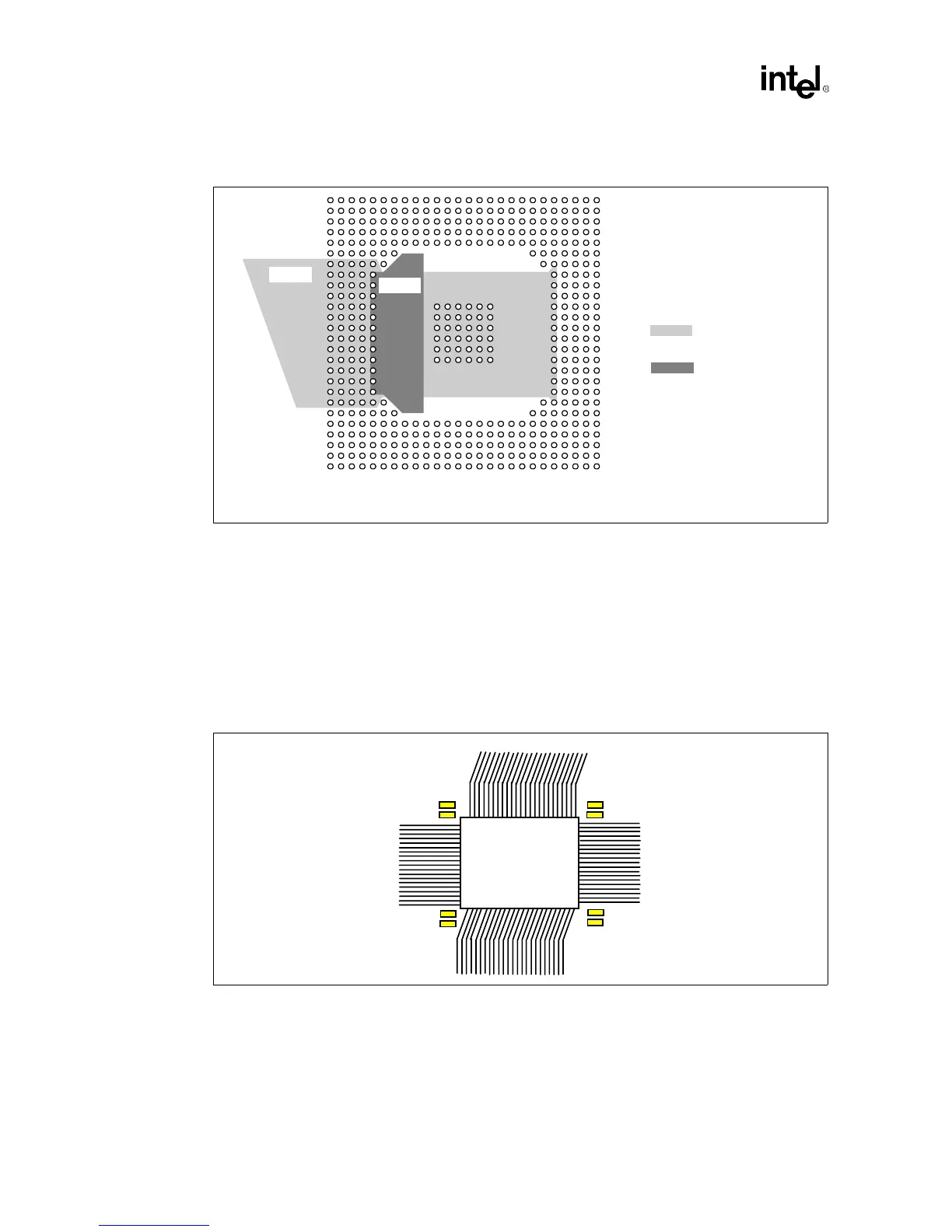
2.2.3.4 Decoupling
Decou
lin
ca
acitors should ideall
be
laced as close as
ossible to the Intel740
ra
hics
accelerator. This means that the best decou
lin
will occur if the ca
acitors are
laced directl
underneath the com
onent. If a sin
le sided board is re
uired and ca
acitors cannot be
laced
underneath the com
onent then decou
lin
is recommended at the corners of the Intel740
ra
hics
accelerator
acka
e. At least a 0.1
µ
F and 0.01
µ
F are recommended for each corner. B
lacin
the ca
acitors in this location all of the traces can “break-out” from the BGA
acka
e on all four
sides.
Figure 2-9. Suggested VCC Planes for the Intel740™ Graphics Accelerator
VCC2
VCC3
VCC2 on VCC Layer
VCC3 on Secondary Side
Signal Layer
vcc_pl.vsd
Figure 2-10. Intel740™ Graphics Accelerator Decoupling
0.1uF
0.01uF
0.1uF
0.01uF
0.1uF
0.01uF
0.1uF
0.01uF
Intel740
Graphics
Accelerator
(468 BGA)