Intel740™ Graphics Accelerator Design Guide
5-3
Mechanical Information
The dimensions shown in Figure 5-3 should be kept in mind when placing the VMI Headers. The
reference DVD daughter cards will be designed for a maximum graphics board component height
of 0.2”. If the component height exceeds these dimensions underneath the daughter card, the
daughter card may not fit.
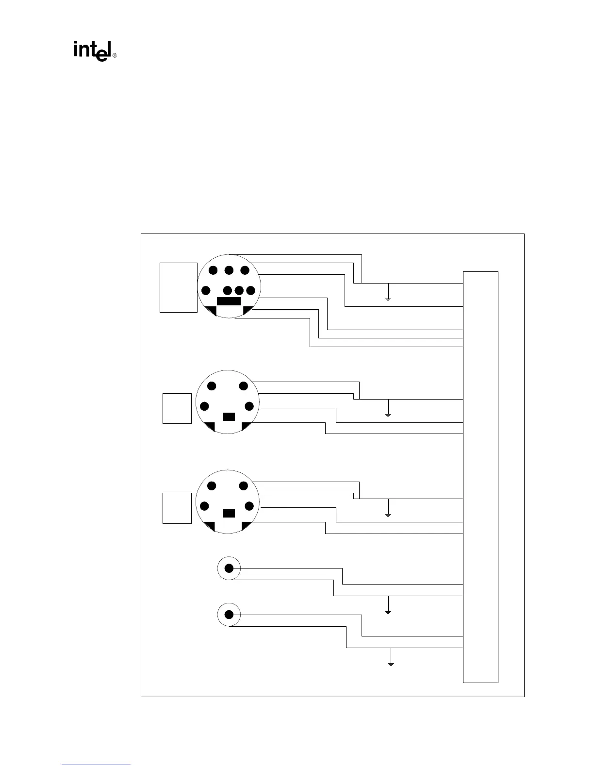
5.4 50 Pin Video Connector
The following diagram is a pinout view of the 50 pin video connector illustrating the different
video connections which can exist.
Figure 5-4. 50 Pin Video Connector Schematic
1 GND
2 GND
3 CVBS
4 NC
5 I2CSCK
6 12V
7 I2CSDATA
1 GND
2 GND
3 Y
4 C
1
2
3
4
5
6
7
1
2
3
4
1 GND
2 GND
3 Y
4 C
1
2
3
4
S-Vidoe In
S-Video Out
Composite Video In
Composite Video Out
Tuner Connector