Revision 0.91
11
SO-DIMM Module — Unbuffered SDRAM/SGRAM Graphics
6.3 Resistor Strapping Options
Three resistor straps are used to indicate the synchronous clock frequency (period) and memory
timing. Timing information for each clock frequency is indicated in the section titled Memory
Timing. Memory modules must meet all timing requirements within the specified operating
environment.
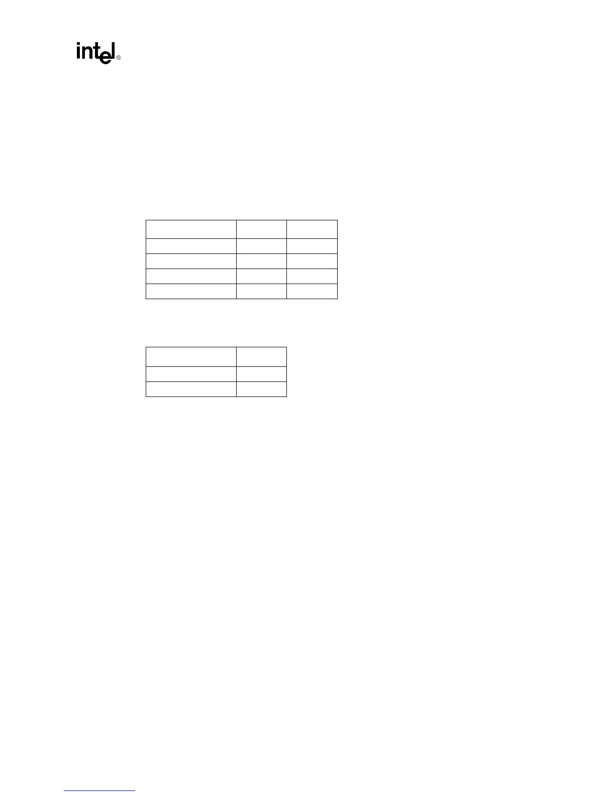
6.3.1 Clock Frequency and Memory Timing
6.3.2 CAS Latency
A logic low (0) indicates that the resistor strapping is tied to ground (Vss). A logic high (1)
indicates that the resistor strapping is tied to Vcc. Resistors should be a 4.7 Kohm resistor on the
DQ lines.
6.4 Serial Presence Detect EEPROM
This EEPROM is optional on the module. For additional information, refer to the Intel document
66 MHz Unbuffered SDRAM SO-DIMM Specification.
Cycle Time DQ30 DQ29
15 nS 0 0
12 nS 0 1
10 nS 1 0
8 nS 1 1
CAS Latency DQ31
30
2 and 3 1