Assembly
Poweredseatingaccessories
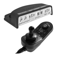
4–waybuttonswitch
•4switches
•DB9connector
4–waytoggleswitch
•4toggledirections
•DB9connector
10–wayswitch
•Hardware-only
modulethatprovides
simple,directaccess
topoweredseating
functions
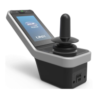
DLX-FKEY01
•Forsystemswithone
physicalactuator
•Poweredseating
controlthroughegg
switch,stereobutton
switchorstereotoggle
switch
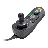
DLX-FKEY02
•Forsystemswith
twoormorephysical
actuators
•Poweredseating
controlthrough4-way
buttonswitchor
4-waytoggleswitch
DLX-GYR100
LiNXG-Tracmodule
•stabilizeswheelchair’s
drivingbehaviour
DLX-USB02
LiNXUSBcharger
•2USBchargerports
•1Achargingcurrent
perport
•Protectiverubber
bungs
DLX-TILT200–A
Anglesensor
•measuresbackrest
angle
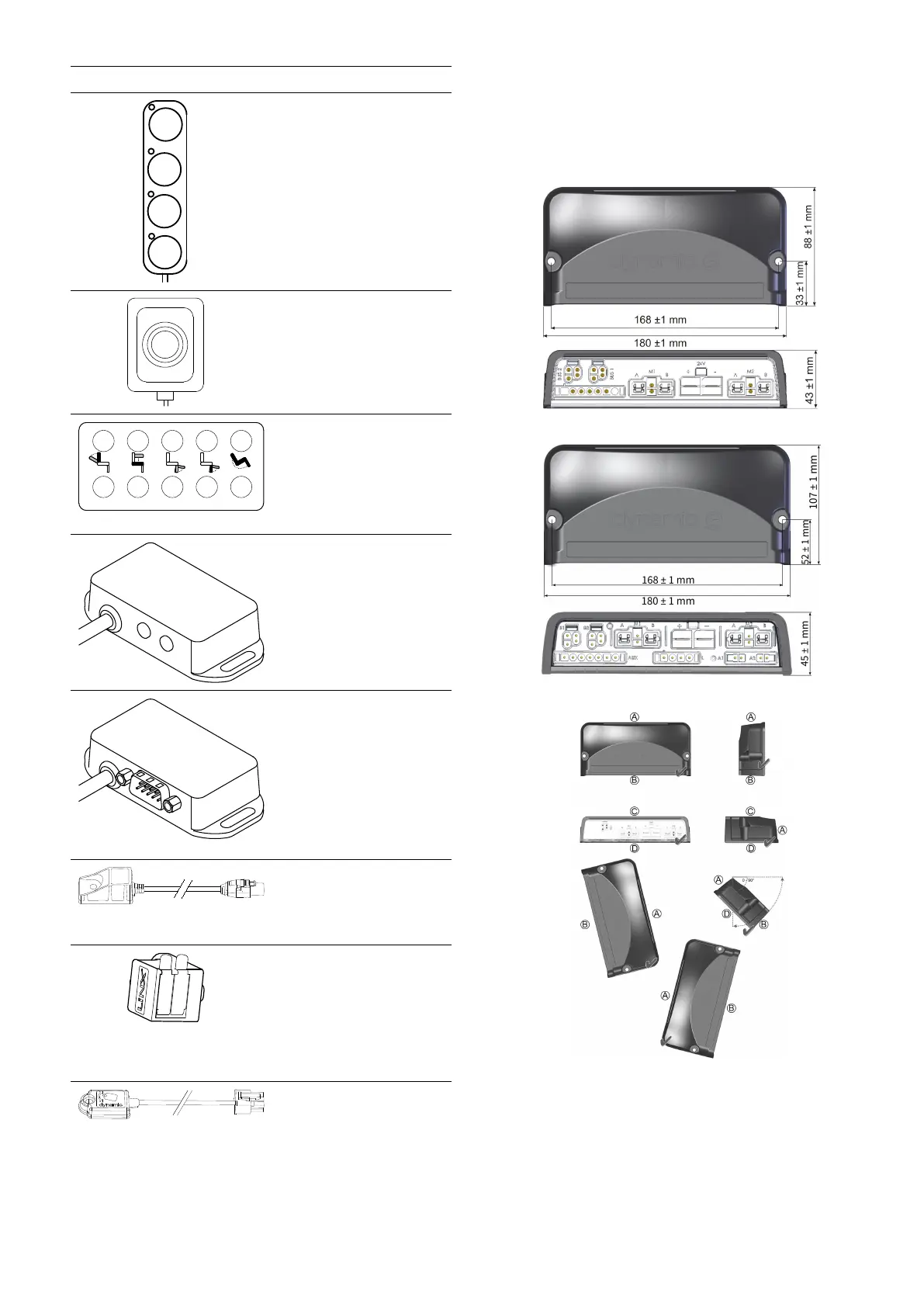
3.4Powermodulemounting
Themountingorientationofthepowermodulethatis
speciedbyInvacareperwheelchairmodelmustbekept.
Dimensionsofthepowermodules
DLX-PM60,DLX-PM75,DLX-PM120
DLX-PM75AL,DLX-PM120AL
Correctmounting
A
Rear
B
Connectors
C
Top
D
Base
Thepowermodulescanbeplacedonitssideoratan
angle.Whenplacingthepowermodulesatanangle,
1605129-G
11