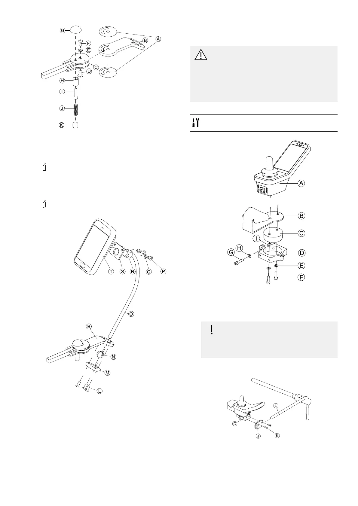
Assembly
Fig.3-35
1.ConnectslipstickerAwithjointarmBandinsert
intosupportC.
2.FixwithsleevenutD,washerEandscrewF.
ApplythreadlockingadhesivetoscrewF.
3.InsertlockingboltHandcompressionspringI
throughsupportCandjointarmB.
4.FixwithlockingknobGandgrubscrewJ.
ApplythreadlockingadhesivetogrubscrewJ.
5.
Fig.3-36
InsertbracketOintojointarmB,clampballNand
clampringM.
FixwithscrewsL.
6.MountremoteTtosupportplateSandclamping
bushRwithwashersQandscrewsP.
3.10MountingPrimaryRemotesto
NucleusMidlineHolder
CAUTION!
RiskofInjuryandDamage
Remainingburrsandmissingendcapsafter
modicationsonrods,suchasshortenedrod,
canleadtoinjuryordamage.
–Deburrcutaftercuttingexcessivelength.
–Re-installendcapafterdeburring.
–Checkendcapfortighttting.
MountingDLX-REM110,DLX-REM2XX,DLX-REM400
•4mmAllenkey
•8mmwrench
1.
Fig.3-37ExampleofDLX-REM400adjustment.DLX-REM110,
DLX-REM211andDLX-REM216areadjustedthesameway.
MountremoteAwithsupportBandsupportdrum
CtoclampDwithscrewsFandwashersE.
2.
Riskofdamagetotheremote
Themaximumtorquetotightenthescrew
is1Nm.
–Donotexceedthisratingasitmay
damagetheremote.
FixsupportdrumCinclampDwithscrewG,washer
HandnutI.
3.
Fig.3-38ExampleofDLX-REM400adjustment.DLX-REM110,
DLX-REM211andDLX-REM216areadjustedthesameway.
PullclampbracketJovernucleusL.
4.AttachclampDtoclampbracketJandxeverything
withscrewsK.
1605129-G39