Assembly
1.
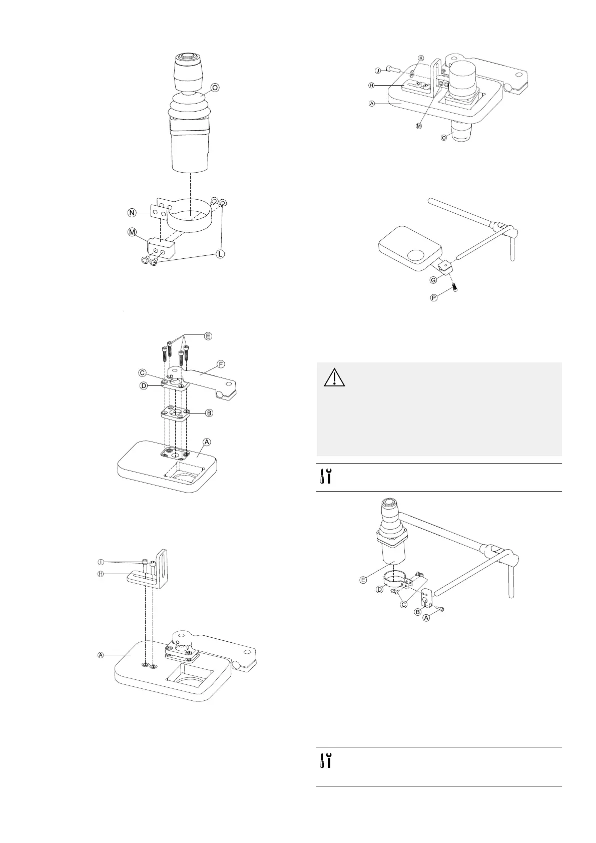
Fig.3-65
InsertjoystickOinclampN,pullclampoveradapter
blockMandxwithscrewsL.
2.
Fig.3-66
InsertclampplateBintocutoutontrayA.
3.FixclampplateB,clampballCandupperclamp
plateDwithscrewsE.
4.
Fig.3-67
MountanglebracketHwithscrewsItotrayA.
5.
Fig.3-68
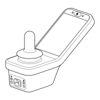
InsertremoteOintotrayA.
6.FixadapterblockMtoanglebracketHwithscrewJ
andwasherK.
7.
Fig.3-69
PullhitchmountGovernucleusandtightenwith
screwP.
NucleusOnlyMount
CAUTION!
RiskofInjuryandDamage
Remainingburrsandmissingendcapsafter
modicationsonrods,suchasshortenedrod,
canleadtoinjuryordamage.
–Deburrcutaftercuttingexcessivelength.
–Re-installendcapafterdeburring.
–Checkendcapfortighttting.
•1/8inchAllenkey
•5/32inchAllenkey
Fig.3-70
1.PulladapterblockBovernucleusandtightenwith
screwA.
2.InsertremoteEintoclampD.
3.MountclampDtoadapterblockBwithscrewsC.
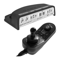
3.12.3MountingtheMicroExtremityControl
Joystick
LateralTrayMount
•1/8inchAllenkey
•5/32inchAllenkey
•3/16inchAllenkey
1605129-G
47