PLDC01938
REVISION 00
01/06/2011
TECHNICAL DEPT.
Stavale
- date 05/09/2011
96/195
7
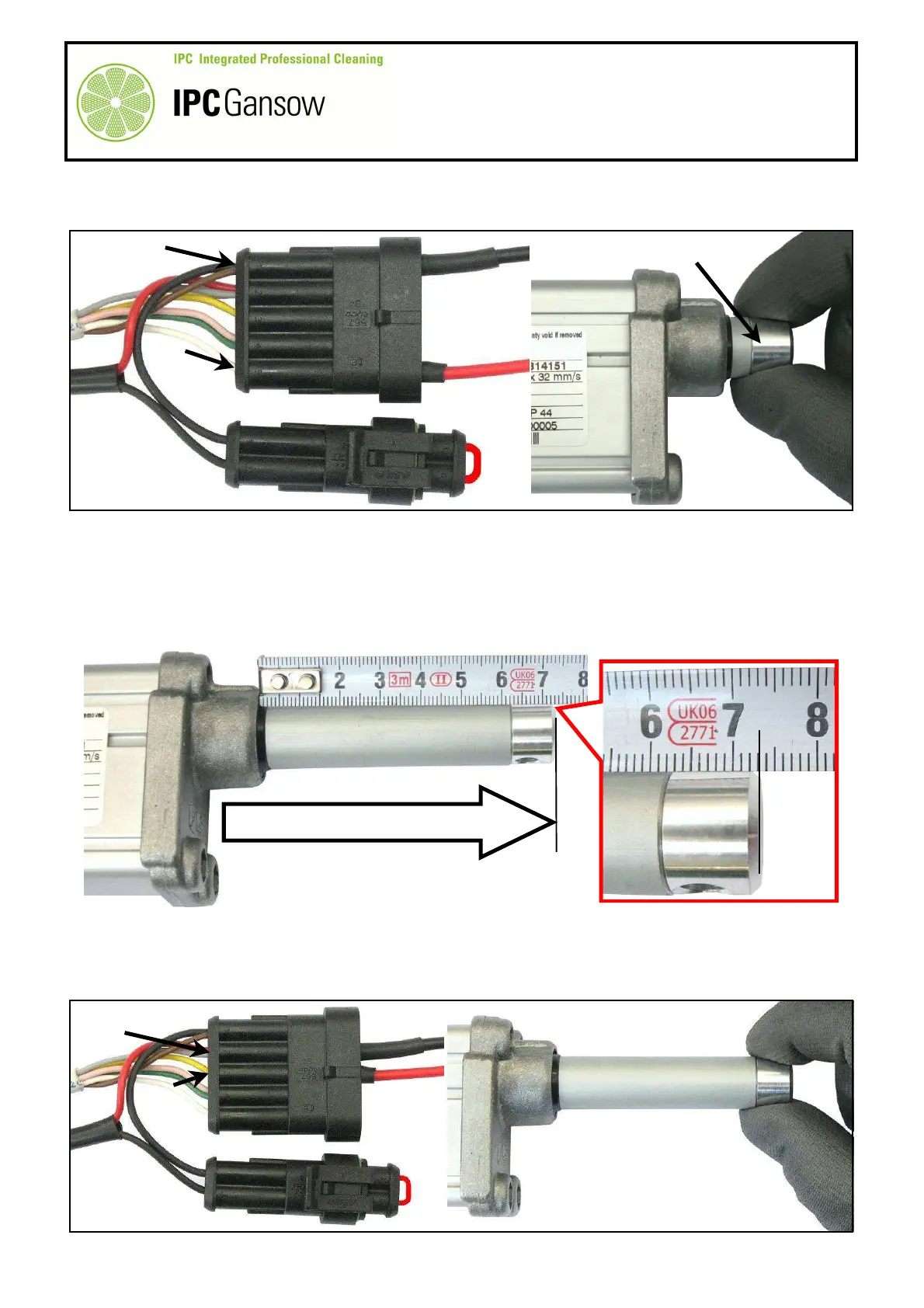
Connect the red wire D1 to the terminal of the white wire B5 and the black wire D2 to the terminal of the
black and brown wires B1 of the connector B.
8
Hold the rod A1 of the actuator A with one hand to prevent it from turning.
9
Connect the other end of the red wire D1 to the positive pole of the battery and the other end of the black
wire D2 to the negative pole (a 6 V - 24 V battery is sufficient, providing it is charged and of a good capacity).
10
If the actuator A is operating correctly, the rod A1 will start moving, emerging from the body of the actuator.
Allow the micro switch to stop the movement of the rod A1.
11
Travel of the rod A1 is ~ 59 mm, so measuring it from the edge of the body of the actuator A should give a
maximum length of 73 mm ± 2 mm.
12
Proceed to verify operation of the micro switch when the stem A1 retracts into the actuator body A.
13
Connect the red wire D1 to the yellow wire B3 and the black wire D2 to the red and grey wires B2 of the
connector B.
14
Hold the rod A1 of the actuator A with one hand to prevent it from turning.
A1
A
1 2 3 4 5
1 2
D2
D1
B
C
B5
B1
TRAVEL ~59 mm / LENGTH 74 ± 2 mm
A
± 2 mm
PHOTO 204
D2
C
B
B2
B3
A
A1
PHOTO 205
E
1 2 3 4 5
1 2
 Loading...