PLDC01938
REVISION 00
01/06/2011
TECHNICAL DEPT.
Stavale
- date 05/09/2011
98/195
24
Check that the motor Z of the actuator A is functioning correctly (it is not necessary to check its function in
the opposite direction), then proceed to control operation of the internal micro switches X and Y.
Checking operation of the internal micro switches
You do not need to remove the protective cover to check operation of the micro
switches in the body of the actuator as they produce an audible sound when
actuated.
The following photographs show the inside of the actuator to give an idea of how the
micro switches work in the various situations.
25
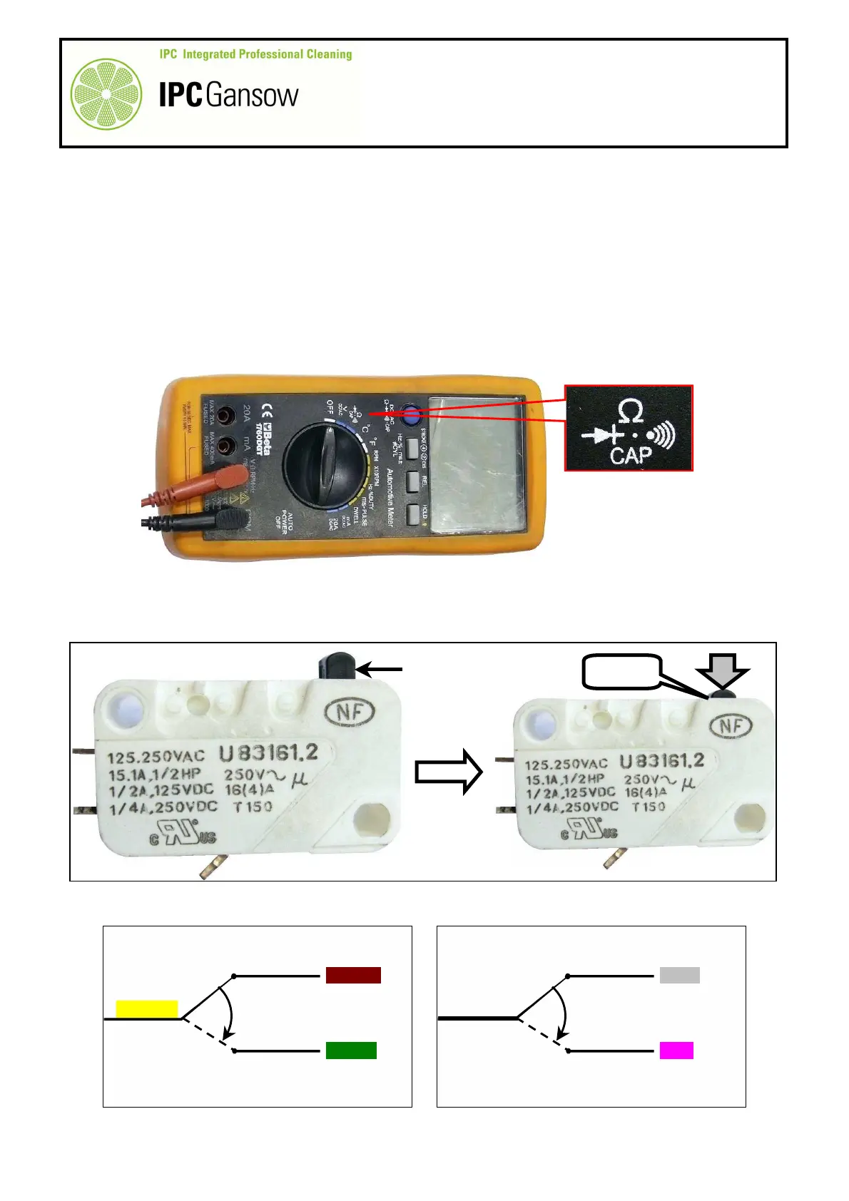
Obtain a digital multimeter with a continuity measurement function, see photograph below.
26
By rotating the rod A1 by hand, check that the cam K on the rod is in the correct position (under the bottom
X or top Y micro switch) by listening for the mechanical click emitted by the micro switches when the
actuator button X1 - X2 is pressed.
27
The six wires are connected to the two micro switches X and Y as shown in the diagram below.
NO
YELLOW
BROWN
GREEN
X
NO
WHITE
GREY
PINK
PHOTO 208
PHOTO 209
X1 – Y1
X - Y
X - Y