PLDC01938
REVISION 00
01/06/2011
TECHNICAL DEPT.
Stavale
- date 05/09/2011
99/195
28
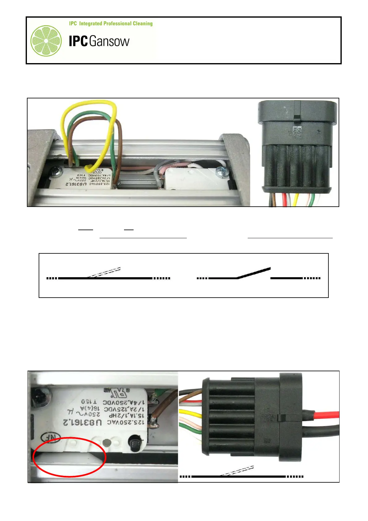
Check correct operation of the micro switches X and Y by means of the connector B and the two wires D1 -
D2.
29
Before starting testing, pay attention to the symbols (not conventional) given below to indicate
where there must and must not be continuity.
30
“OK” means that the presence of continuity is correct, “NO” means that the absence of continuity is correct.
31
Manually position the cam K of the rod A1 under the micro switch X1 (completely screwed up).
32
Connect the plug on the red wire D1 to the terminal of the yellow wire B3, position 3 of the connector B.
33
Connect the plug on the black wire D2 to the terminal of the green and pink wires B4, position 4 of the
connector B.
34
Connect the opposite ends of the wires D1 and D2 to the digital multimeter and check electrical continuity.
35
If the digital multimeter display moves from the initial position, there is continuity, move onto the next point.
Otherwise replace the micro switch or actuator.
Continuity present
PHOTO 213
PHOTO 212
1 2 3 4 5
X
OK
D1
D2
B3
B4
K
B
X
X1
3 4