PLDC01938
REVISION 00
01/06/2011
TECHNICAL DEPT
Stavale
- date 05/09/2011
155/195
8
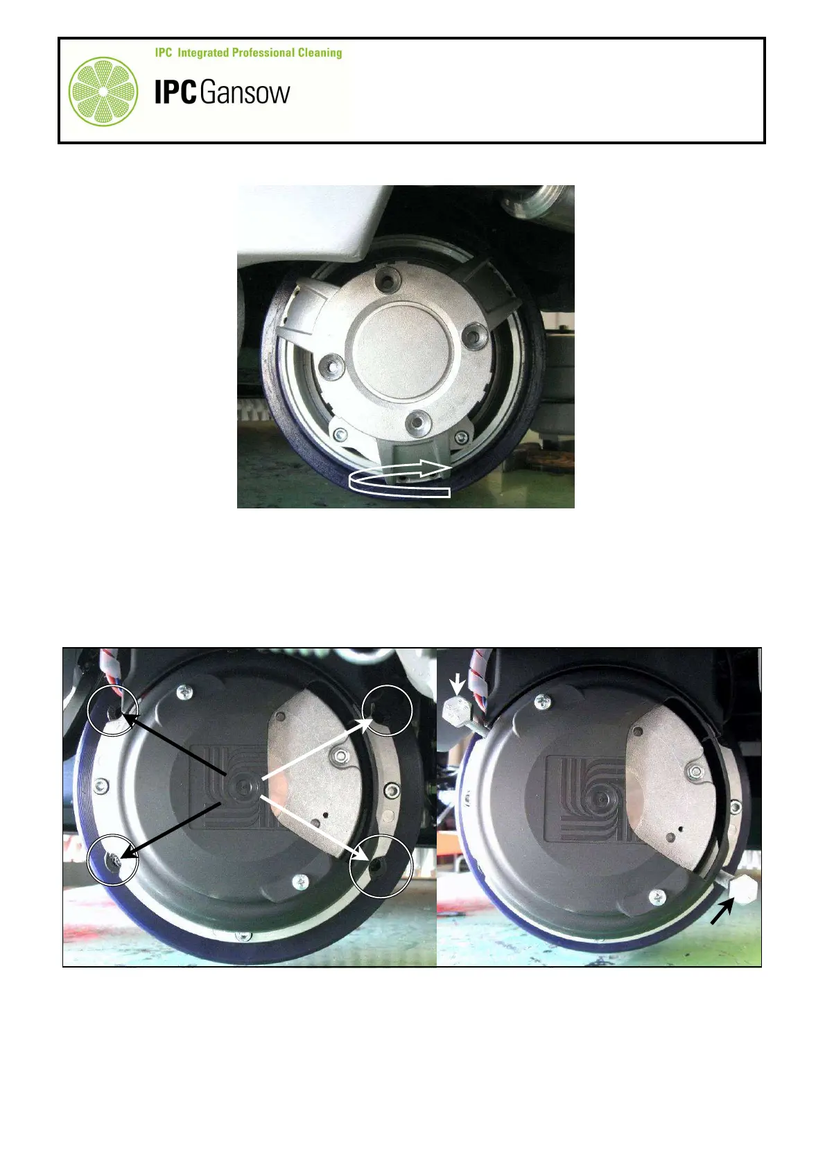
Turn the motor wheel to the opposite side and identify the four (4) threaded holes A6 provided specifically as
extractors to facilitate removal of the rubber tyred ring.
9
Insert two (2) M10 screws B with at least 80 mm of thread and screw them up almost simultaneously in order
to push the rubber tyred ring A4 outwards.
10
If necessary, remove the duct cover A7 to enable the screws B to be screwed up to their full length.
PHOTO 322
A6
PHOTO 323