PLDC01938
REVISION 00
01/06/2011
TECHNICAL DEPT
Stavale
- date 05/09/2011
158/195
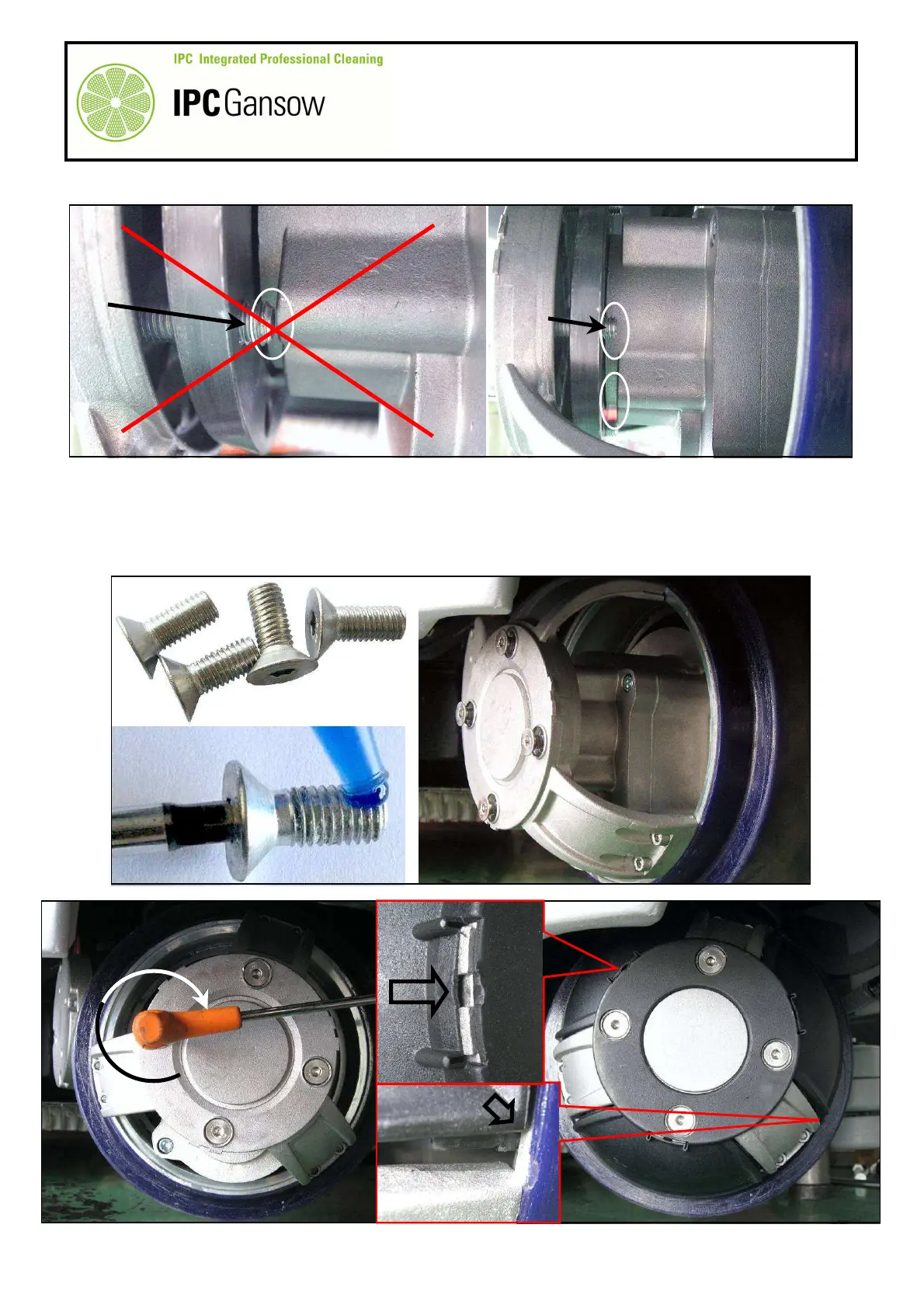
10
When screwing up the four screws C, pay attention to the position of the drive hub A8 with respect to the
motor wheel reduction unit casing.
11
With the drive coupling A5 near the drive hub A8, unscrew the screws C and screw up the new screws A2
(VTVT01352) provided with the new rubber tyred ring.
12
Apply thread lock on the first threads of the screws before screwing up.
13
Screw up the new screws A2 with moderation using a maximum torque of 18.0 nm (~ 1.8 kgm).
14
Centre and remount the plastic protection A1, paying attention to the connectors.
PHOTO 328
A8
Max 18 Nm
PHOTO 330
PHOTO 329