PLDC01938
REVISION 00
01/06/2011
TECHNICAL DEPT.
Stavale
- date 05/09/2011
6/195
19
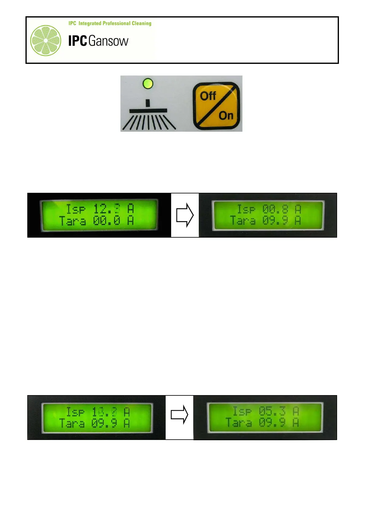
Press the manual brush button E to operate the brushes.
20
Read the draw value. The board provides two values, both very important. The first row (Isp) gives the draw
of the brush motors during the washing phase, in this case without the brushes. The second row (Tara)
gives the draw value of the brush motors without load (with or without the brushes).
When the brushes start rotating, the control unit reads the draw value at start-up and the value
an instant before the brush actuator lowering command is given. It then calculates the
mathematical mean of these two values, known as TARA.
Once the TARA value has been calculated, while the actuator is lowering the head, the control
unit also calculates the pressure to be exerted on the brushes as a function of the set value (in
this case in "Program 1").
The brushes are pushed towards the floor by the actuator commanded by the control unit until
the brush motor draw reaches the value calculated, considering the set tolerance (T0.X in this
case in "Program 1").
During normal use, the control unit dedicates a maximum of 50 A to the brush motor and limits
output if the current draw exceeds 65 A for more than 10 (ten) seconds.
The control unit controls the head raising and lowering actuator in order to maintain the
set pressure. In output limitation situations, the control unit commands raising of the
head to the minimum acceptable height. If the draw does not drop within ten seconds, the
control unit turns off current to the brush motors and brings the head to the standby
position.
No error message is displayed.
If the brush lowering command is given while the output limitation situation is still present,
the head will remain in the standby position. The shutdown may be caused by the motor
seizing (bearings, rotor) or mechanical interference (brushes jammed).
In this case, in order to read the draw value calculated, the control unit commands descent of
the actuator to the maximum extent of its travel until it touches the limit micro switch which also
indicates the maximum limit of brush wear, providing the information on the display and via a
buzzer.
PHOTO 14
i
i
PHOTO 15
PHOTO 16
i
i
i