PLDC01938
REVISION 00
01/06/2011
TECHNICAL DEPT
Stavale
- date 05/09/2011
165/195
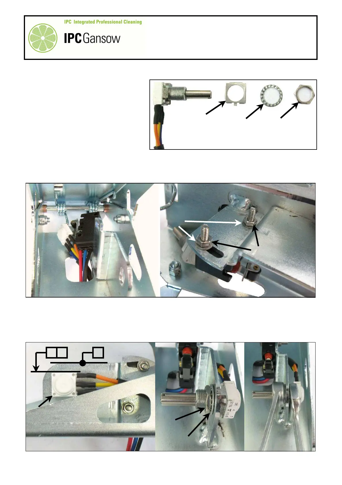
Replacing
7
If present, eliminate the plate B1 with
mechanical anti-rotation lock.
8
Insert the wiring of both the micro switch C and the potentiometer B into the opening in the base of the
accelerator pedal.
9
Mount the micro switch C, paying attention to the 4 mm dia. washers C1, screw up the M4 nuts C2 without
tightening excessively.
10
Mount the potentiometer B horizontally, placing the output wires parallel to the plane of the bottom pedal and
facing the axis of pedal rotation.
11
Always insert the toothed washer B2 between the pedal plate and the nut B3 and tighten the nut with
moderation.
12
Tighten the nut B3 of the potentiometer B with moderation, using a no. 13 spanner to hold the
potentiometer in position (parallel to the base of the pedal) and a no. 12 spanner to tighten the nut B3.
C
B
C1
C2
B1
B2 B3
PHOTO 344
B
B
B3
B2
12